
-
Consideration of second order effects (p-δ and p-Δ) is under user control.
-
The non-linear static calculation is automatically applied, considering the static vertical loads and the second-order effects applied incrementally to the carrier system. The internal forces and strains obtained from this calculation are automatically taken into account as the initial condition of the pushover analysis.
-
Non-linear deformations are automatically taken into account as a starting condition in the evaluation of new buildings and existing buildings.
-
Plastic deformations with ductile behavior are compared with the limit values for the selected performance level. Deformations and limit values are calculated automatically for new and existing buildings.
-
Ductility checks are made automatically on columns, beams and curtains. The cutting force with brittle behavior is compared with the internal force limit values for the selected performance level.
ICONS
E d (H) = Horizontal earthquake effect on the basis of the designwith strike-joint application
E d (X) = Earthquake effect in (X) direction
E d (Y) = Earthquake effect in (Y) direction
E d (Z) = Vertical earthquake effect
G = Fixed load effect
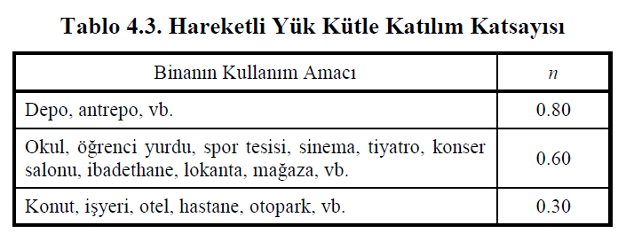
n = Live load contribution factor
Q = Live load effect
Q e = Effectiveliveload effect
S = Snow load effect
p-δ =Second-order effect caused by the curvature of the element under the effect of axial force and bending moment
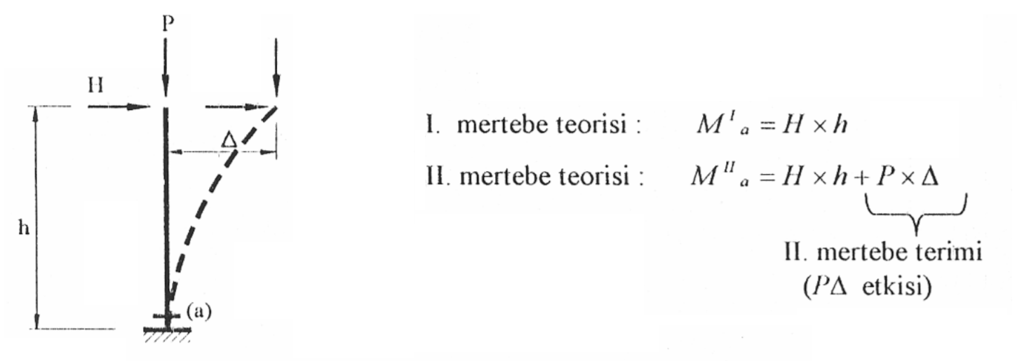
p-Δ = Second-order effect due to the axial force effect as a result of the displacement of the element nodal points
According to TBDY 5.6.1.1 , within the scope of this regulation, Constant Single Mode Pushove Analysis Method, Adaptive Single Mode Pushover Analysis Method and Incremental Response Spectrum Analysis (IRSA Method) can be used in non-linear earthquake calculation.
According to TBDY 5.6.1.2 , as in all non-linear methods, static calculation is made in the initial step of the calculation, if non-linear increments under non- earthquake loads . In this case, second-order effects, p-δ and p-Δ should be considered.
According to TBDY 5.6.1.3 , the plastic deformations corresponding to the ductile behavior obtained as a result of the thrust analysis and the internal forces corresponding to the non-ductile behavior (eg shear force) are compared with the allowable limit values for the selected performance level.
In the calculation for plastic deformations corresponding to ductile behavior, Plastic Deformation and Internal Force Limits for New Buildings and Plastic Deformation and Internal Force Limits for Existing Building differ due to the different material models. For this reason, these limit values are calculated automatically according to the selected building condition, compared with the plastic deformations and the building performance is determined. For internal forces opposing brittle behavior, ductility check of the elements is done for new and existing buildings.
According to TBDY 5.2.2.2 , if the Evaluation and Design Based on Strain (GDT) approach is applied to the structure, the earthquake calculation to be made with nonlinear calculation methods (any thrust analysis or nonlinear analysis in the time domain) should be E d (H) before Non -linear static calculation in which static vertical loads other thanwill be done. The internal forces and strains obtained from this calculation are taken into account as the initial value in the horizontal earthquake calculation. In this case, the non-linear static calculation applied using vertical loads is made according to the following loading condition. The internal forces and strains obtained as a result of this analysis are taken into account as the initial value of the horizontal earthquake calculation.
G+nQ+0.2S+0.3E d (Z)
In this loading case, n is the Live Load Mass Participation Coefficient as explained above and is calculated from Table 4.3 . For example, before applying the pushover analysis to a house (n=0.3) where there is no snow load, the nonlinear static calculation is applied incrementally under the following loading condition as the initial step (i=0) .
G+0.3Q+0.3E d (Z)
In this nonlinear static calculation , the nonlinear behavior of the structure in terms of geometry and material is taken into account.
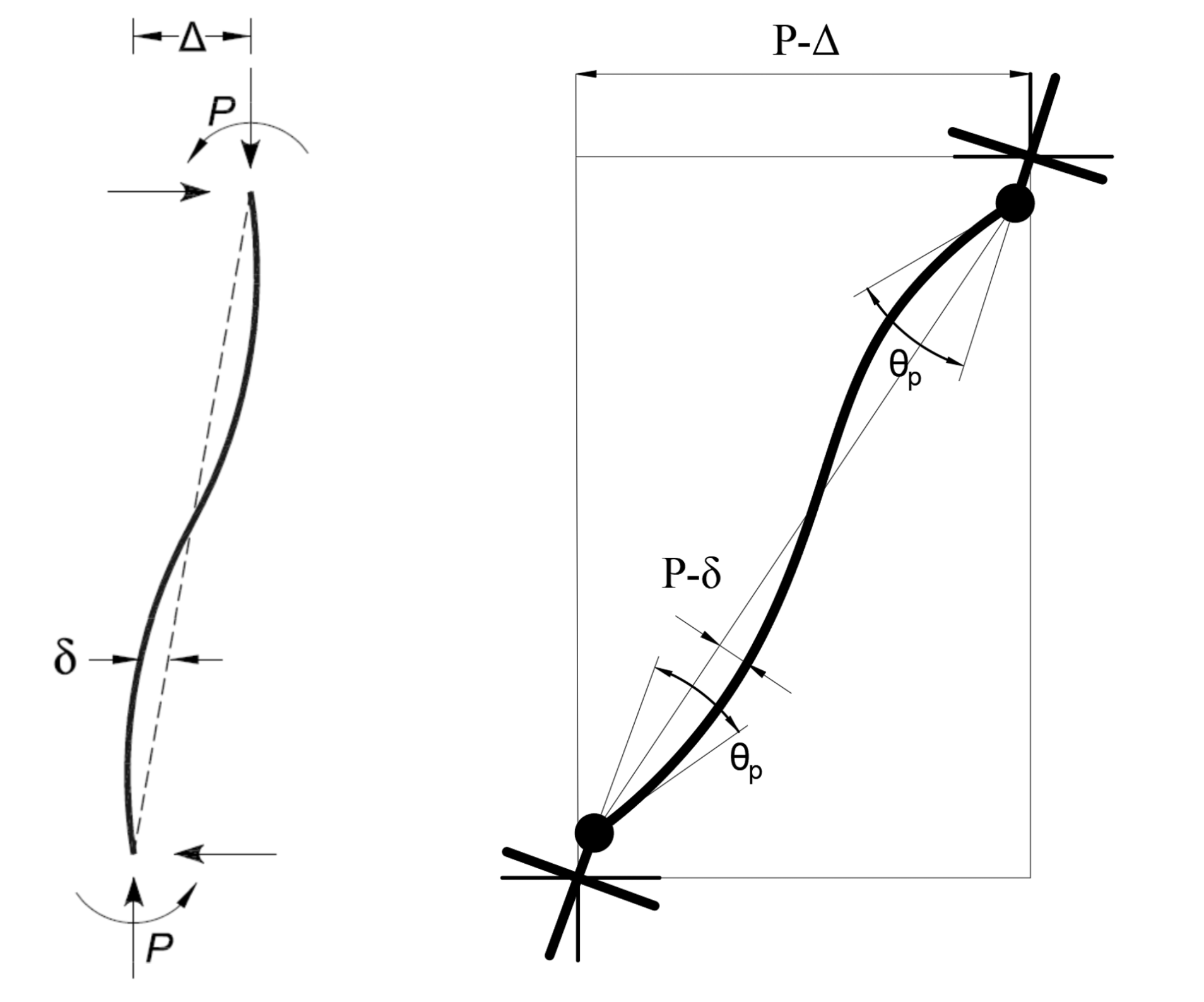
In the non-linear analysis in terms of geometry, second-order effects that occur due to the axial forces occurring in the building elements are taken into account. Second-order effects are divided into p-δ and p-Δ. The figure on the right shows how the effects of p-δ and p-Δ are on an element in a representative way. The p-δ effect is caused by the axial pressure force on the element trying to increase the displacement plasm caused by the element's own curvature. The p-Δ effect, on the other hand, creates additional moments in the axial pressure force due to the displacements of the nodal points of the element. p-Δ is explained in more detail in the picture below.
Concentrated Plasticity Model Distributed Plasticity Models
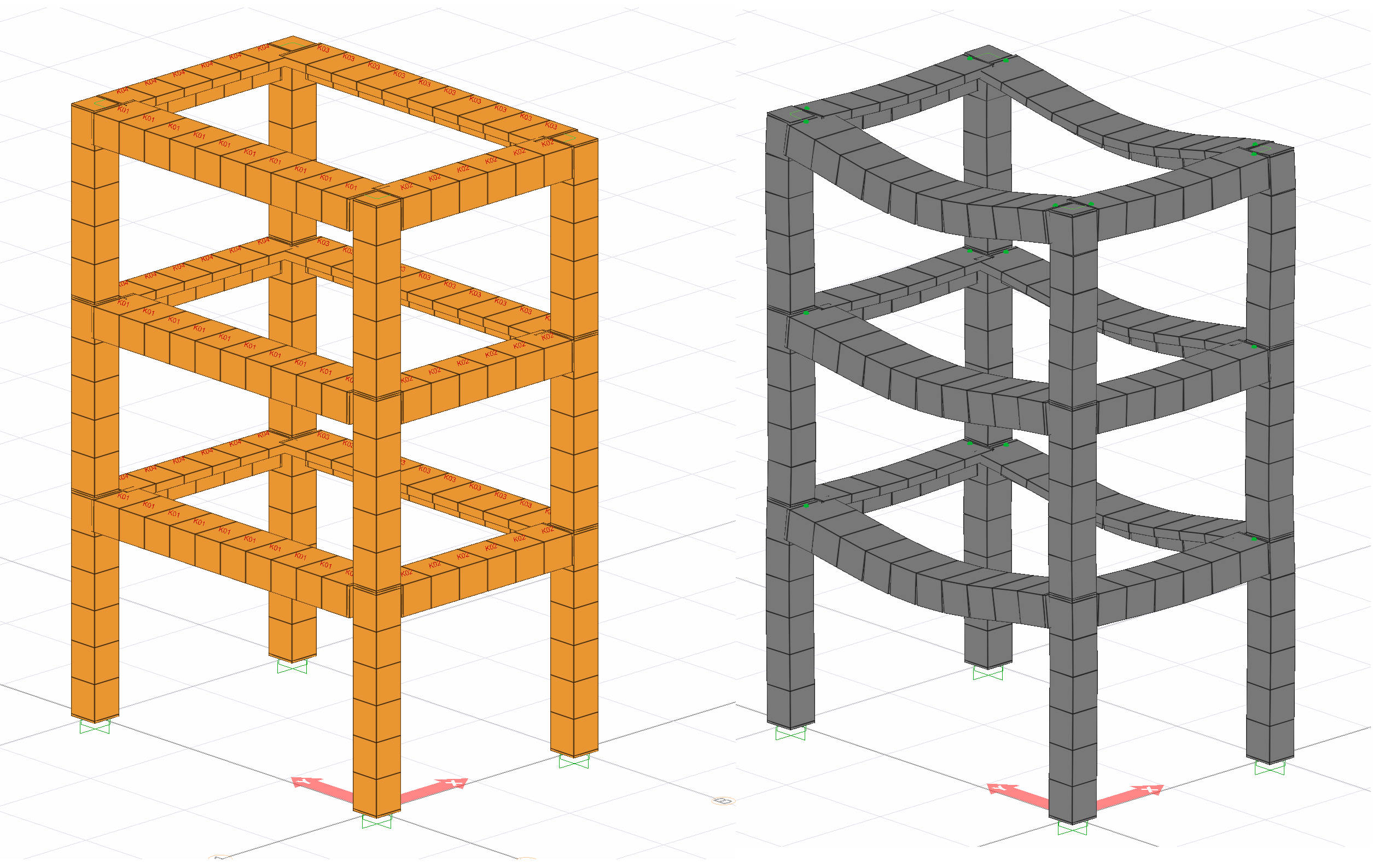
In order to consider the second order effects p- p and p-Δ effects, the analysis is done by dividing the elements sufficiently. In this way, the modified system at the initial or any i th step of the pushover analysis is considered as the initial condition for the next step. The following image shows the analysis model and the modified system, considering the second-order effects of a sample model.
Next Topic
Related Topics