
-
Nonlinear behavior model in columns and beams that can be modeled as rod finite elements The Stacked Plastic Behavior (Plastic Hinge) Model is used and plastic hinges are automatically defined in the middle of the plastic deformation zone.
-
The plastic joint length is automatically calculated to be half the section height.
-
Concrete and reinforcement material models specified in TBDY ANNEX 5A are used in plastic joint sections . In the analysis of new or existing buildings, wrapped-unwrapped concrete and reinforcement models are automatically created.
-
The plastic hinge skeleton curve is created automatically by the moment-curvature analysis using the fiber model.
-
In the effective yield moment calculation, the effects resulting from the axial force and biaxial bending effect are automatically calculated.
-
The fiber model solution is done automatically in the elements.
ICONS
h = Section height
L p = Plastic hinge length
M y = Effective yield moment
M u = Crush moment, power exhaustion moment
M p = Plastic moment
ε c = Unit deformation value of concrete
ϕ = Curvature
ϕ y = Curvature ofyield
ϕ u = pre-collapse curvature, power exhaustion curvature
ϕ p = Plastic curvature prompt, ϕ p = ϕ u - ϕy
θ = Displaced axis rotation
θ p = Plastic rotation request, the largest plastic rotation the section can make
The Piled Plastic Behavior Model is a behavior model created with the assumption that nonlinear bending deformations are concentrated in a small region called a plastic joint . The system is assumed to behave linear-elastic in regions outside the plastic hinge area. In order for the plastic hinge to occur, the sections in this region must have plastic curvature capacity. In addition, this capacity must be used and the resulting plastic deformations must remain at an acceptable level.
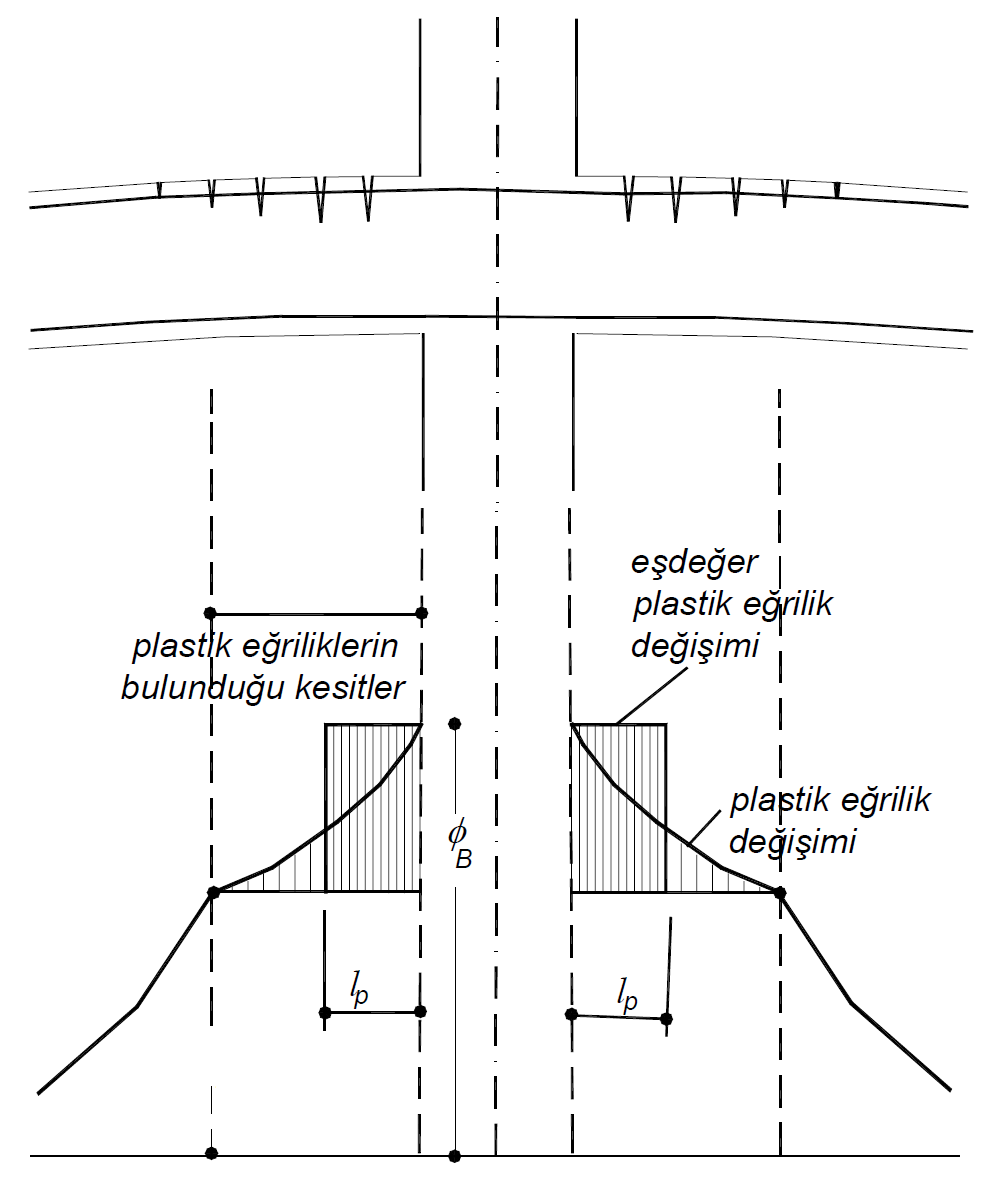
Nonlinear deformations spread over a region of plastic hinge length L p on the rod element . TBDY Article 5.3.1.2 'As stated above plastic hinge length is called plastic deformation of' the length (L p ), cross-sectional height (h) which is calculated as one-half (L p = 0.5H). According to Article 5.3.1.4 of TBDY , the plastic joint should be placed in the middle of the plastic deformation zone . In this case, the plastic hinge from the ends of the defined elements in the clean opening L pIt is defined at a distance of about / 2. The figure below shows the length of plastic hinges formed in the beams in the reinforced concrete column-beam junction . According to the Piled Plastic Behavior Model , the plastic deformations are considered to be along the length L p and the plastic hinge is placed at half the length L p .
Plastic hinges represent plastic deformations of the elements . Therefore, the moment-curvature relationship of reinforced concrete sections is used when defining plastic hinges. In the moment-curvature relationship, the ductility of the cross-sectional behavior, the variation of the cross-section stiffness at different moment levels, whether crushing occurs in the shell and core concrete according to the material model used, the effect of confined concrete in the cross-section, whether the flexural reinforcement is broken, the impact of bending reinforcement on the behavior can be observed. Curvature is a geometric variable that indicates the deformation in the cross section.
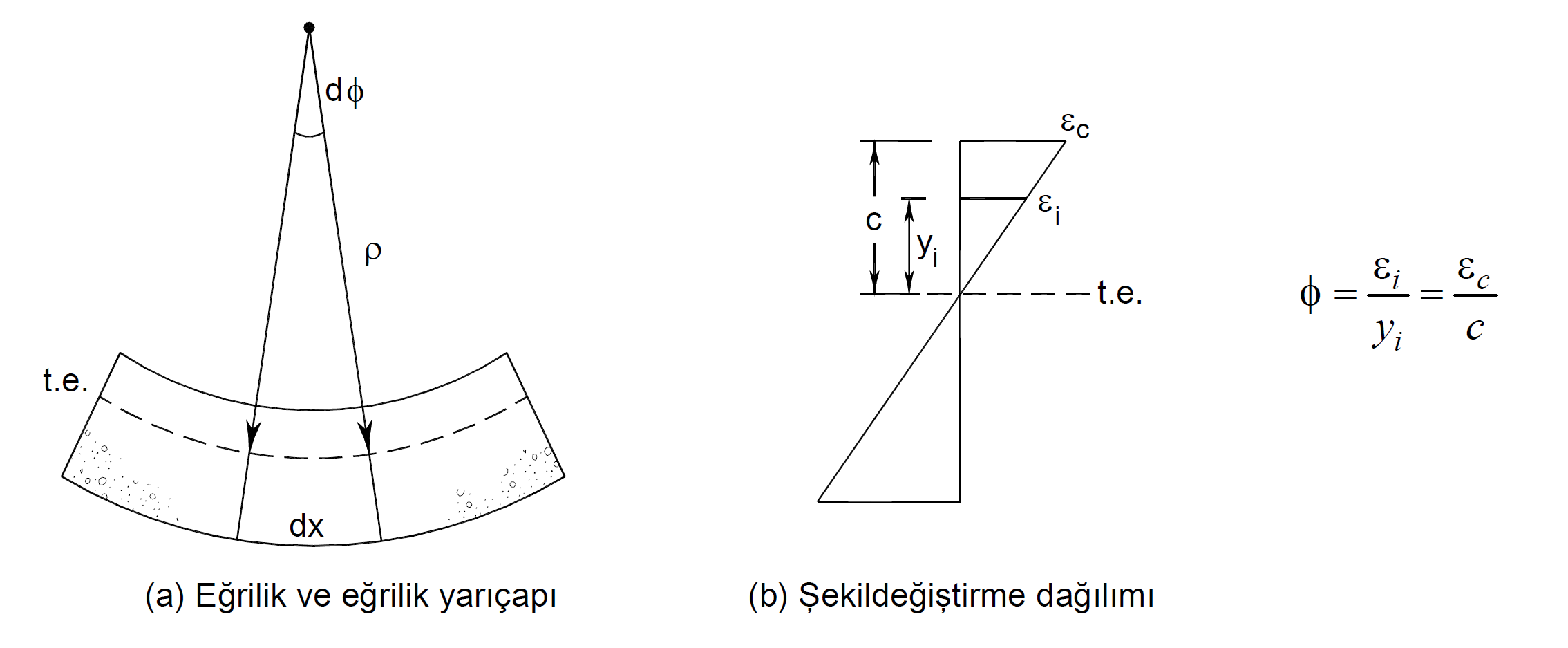
The figure above shows an element part deformed under the influence of bending and axial force and a simple moment curvature relationship. According to the concrete reinforcement material models defined in the moment curvature relationship, in the deformation distribution resulting from each moment value, the unit strain value of the concrete is divided by ε c by the neutral axis height, c value, and the curvature value is obtained. In a section where the deformation distribution is shown in the picture above, the curvature is the angle between two planes.
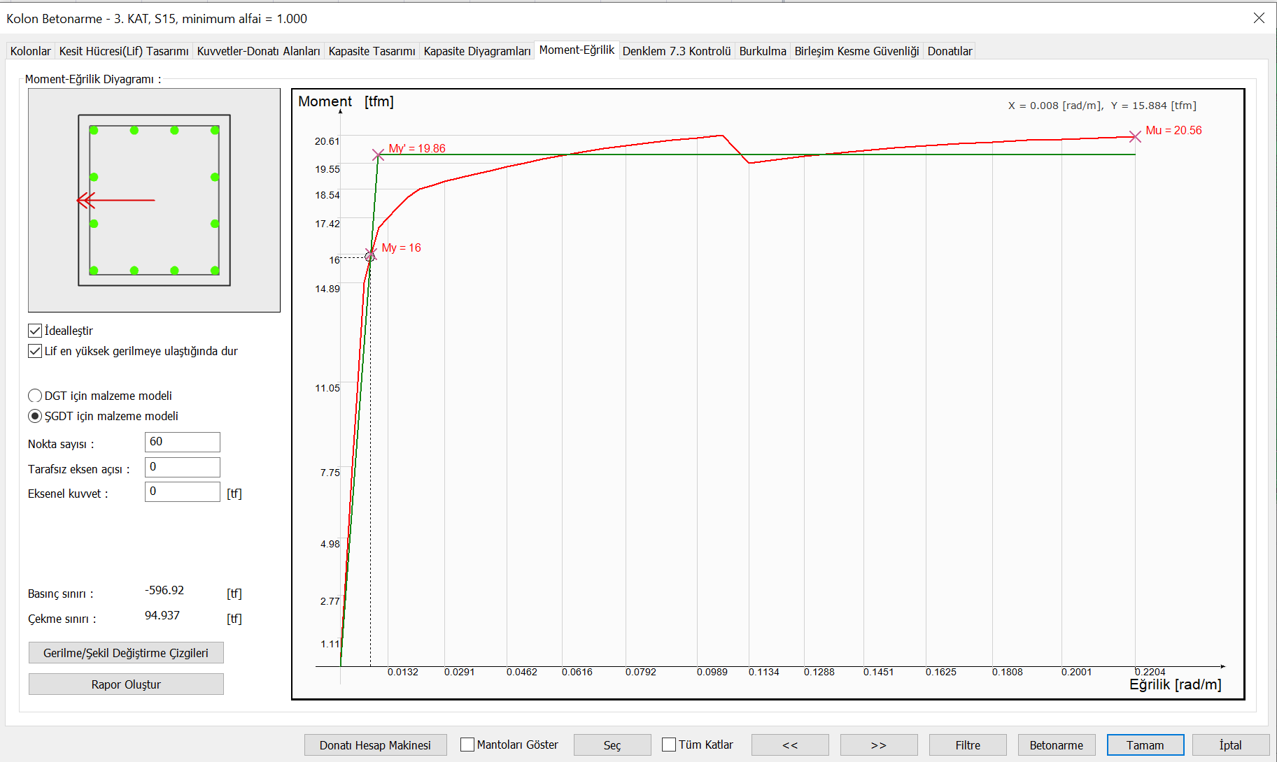
As a result of the moment curvature analysis, the yield moment and yield curvature (M y and ϕ y ) of the reinforced concrete section , the collapse moment of the section and its curvature before failure (M u and ϕ u ) are found. The graph below shows the moment curvature plot of a ductile element.
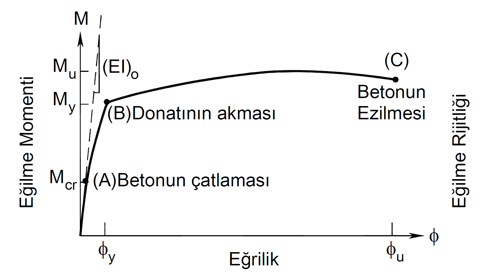
In the moment curvature graph shown in the picture above , M y , ϕ y point is the moment and curvature in the flow of tensile reinforcement of the reinforced concrete section under the effect of tensile bending. For this reason, M y and ϕ y values are named as yield moment and yield curvature. After the cross section reaches this point, it is accepted that the plastic deformations have started. However, for a ductile element, the concrete should not have reached the maximum unit deformation value at this point. The point where the concrete reaches the highest strain value or the rupture strain value of the reinforcement can be accepted as the point where it loses its cross-section strength. Therefore, the collapse of the cross section M u , ϕ uoccurs at the point. In this case, the ductility of the cross section is measured by the ratio ϕ u / ϕ y . When the moment curvature is drawn according to the material models defined in TS500 in the DGT approach , the design moment M u corresponds to the point ϕ u .
General Modeling Stress-Strain Curves for Concrete and Reinforcement Materials
An idealization should be done in order to use the results of the moment curvature plot we have obtained in the definition of plastic hinges . Therefore, the moment curvature graph shown in black below is idealized with the red line using the principle of equal areas.
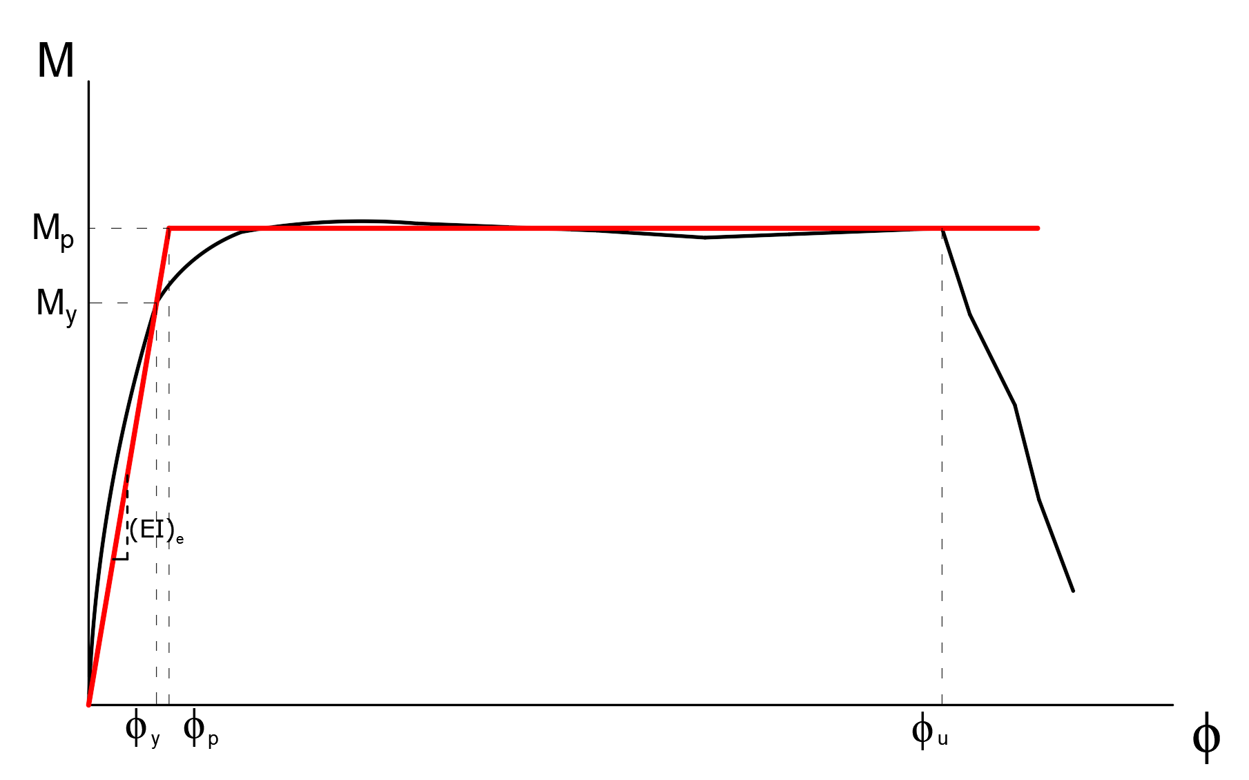
In the above graph, M p is considered as the plastic joint moment. When any nonlinear analysis is done, a plastic joint is placed at this point when the bending moment of the plastic joint reaches the value M p at the defined point . The moment above this point remains constant, but makes a rotation deformation into the state of failure. These rotations made after the moment of yield are called plastic rotations and denoted by θ.
Winding effect is taken into consideration in material models used in moment curvature relation. In the SDDT approach, the winding effect is taken into account as shown in Annex 5A of TBDY . The winding effect creates an increase in concrete compressive strength according to the transverse reinforcement conditions of the section in the plastic hinge area. The following picture shows the interaction between element cross section and moment curvature. In the ŞGDT approach, a confined concrete model is used in the inner part of the element section (inside the area surrounded by a stirrup) and an unwrapped concrete model is used in the outer part.
The relationship between curvature and plastic rotation is as shown in the equation below.
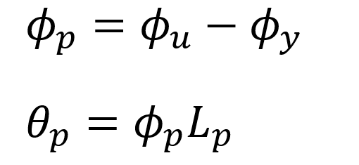
In the above equation, ϕ p value is the greatest plastic deformation curvature of the section obtained by subtracting the yield curvature from the collapse curvature of the section. When the ϕ p value is multiplied by the length of the plastic hinge, L p , the plastic rotation request, in other words, the highest plastic rotation θ p value that the plastic hinge can make without collapse is obtained. This rotation is a collapse deformation of the cross section, and after this point the system cannot continue to bear load.
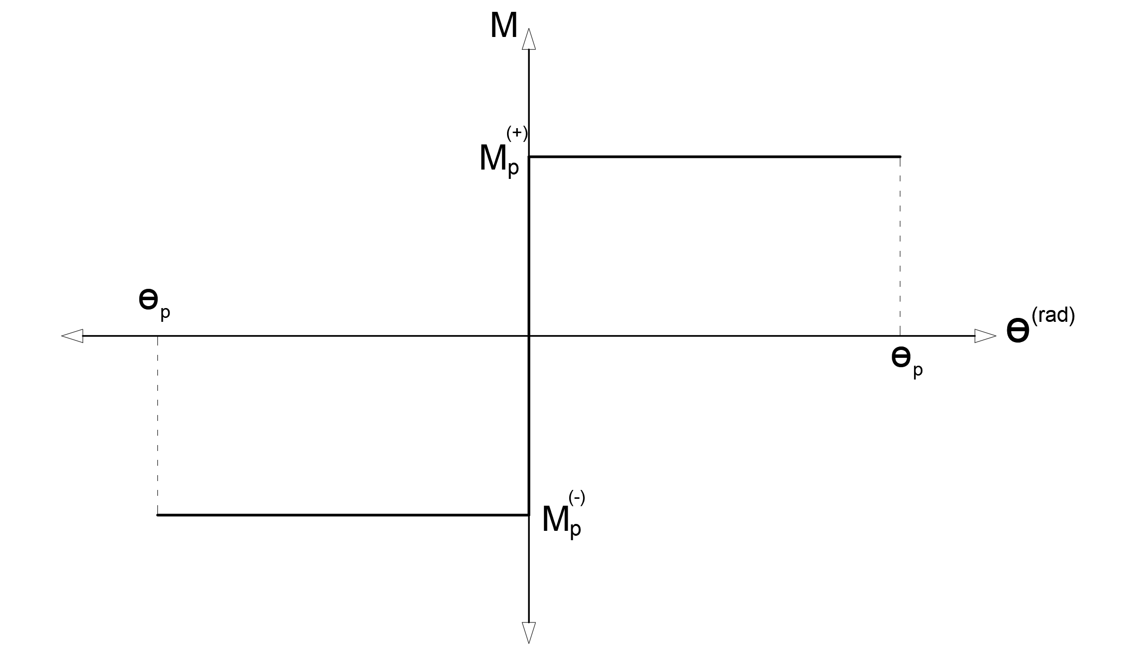
Plastic moment, M p and plastic rotation prompt, θ p frame curve of the torque curve can be drawn with the aid of plastic hinges after being as follows. According to Article 5.3.1.6 of TBDY , the increase in plastic moment due to the increase of plastic rotation can be abandoned. Therefore, the moment will remain constant after the element becomes plastic. The graphic below shows the skeleton curve of the plastic hinge. Since this graph shows only plastic deformations, at moments smaller than the ideal torque or plasticization moment value, the plastic deformation will appear as zero. In TBDY Article 5.8.1.2 , the structure performance is determined according to the plastic deformations on this skeleton curve.
The topics described above are used only for elements that receive bending moments. However, in the elements (column, curtain) where the normal force is also effective besides the bending effect, the normal force causes changes in the moment-curvature relation. When the level of normal force increases, the plastic deformation ability of the element will change, however, it will reach a different rotational value to the collapse state. Along with the normal force, the bending moment in both directions will also change the moment curvature relation, which will indirectly change the plastic deformation capability of the section.
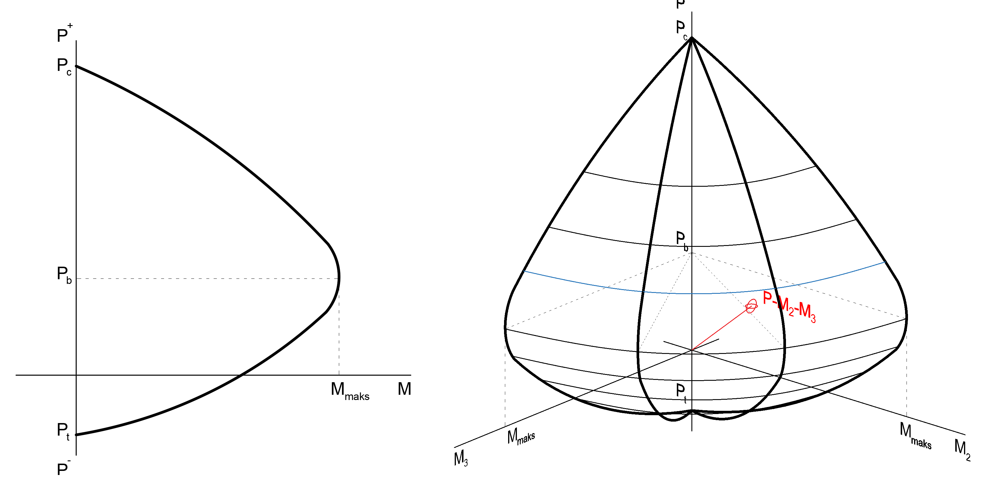
In the elements where normal force and biaxial bending are effective, the plastic hinge should be defined according to the axial force and biaxial bending interaction graph (onion curve) according to the level of the normal force. In the moment curvature analysis , an interaction curve is obtained by determining the yield moment, M y and yield curvature ϕ y separately in the direction of the strong and weak bending axis (M3 and M2) at different normal force levels . In each step of the analysis, the PM 2 -M 3 values at the point where the plastic joint can be formed are checked to see if the cross section reaches the yield curve. PM 2 -M 3 interaction curve Yield moment at each normal force level, M yand thus represents the idealized M p values. The graphs below show the normal force bending moment interaction in two-dimensional and three-dimensional axes.
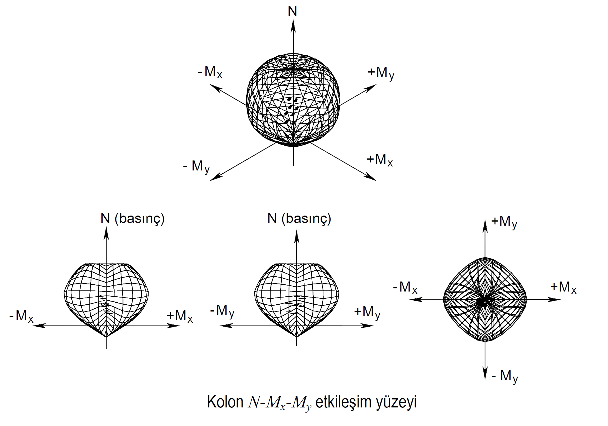
Only plasticization under bending is considered in beams. For this reason, plastic hinges defined in beams are called M3 hinges . In columns and curtains, when there is a normal force and biaxial bending interaction, the plastic joints defined in these elements are called PM2M3 joints .
Next Topic
Related Topics