
With the section dimension command, beam and slab dimensions are made. It becomes active in section windows. One dimension line is formed.
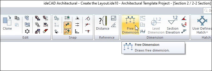
Location of Section Dimension Command
You can access the section dimension command from the Dimension dialog that opens after you enter the Free Dimension command under the ribbon menu Drawings tab Dimension heading .
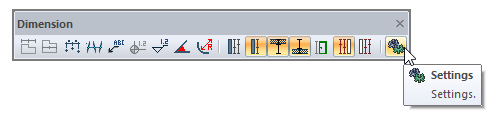
Location of Section Dimension Settings
Enter the section dimension command from the dimension dialog and click the Settings icon.
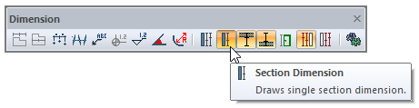
Dimension Toolbar
|
Icons |
|---|
|
Free dimension The free dimension command works. |
|
Intersection dimension The intersection dimension command works. |
|
Label Runs the label command. The dimension label is drawn. |
|
Sectional elevation It is used to make elevation dimension in section and view windows. It is active only in 2D drawing windows. |
|
Angle dimensioning Measures the angle between two objects. |
|
Radius dimension Dimensions objects drawn with a circle or arc and an arc or circle axis as diameter or radius. |
|
Section dimension group Creates a section dimension group. It is active in section and view windows. |
|
Section dimension Creates a section dimensio. It is active in section and view windows. |
|
Include beams Include beams in the section dimension. |
|
Include slabs Include slabs in the section dimension. |
|
Include details Include door/window elements in the section dimension. |
|
Left side Places the section dimension to the left. |
|
Right side Places the section dimension on the right. |
|
Settings When clicked, whichever dimension type is active (inner, outer, intersection, etc.), it opens the dimension settings dialog with parameters related to that dimension. |
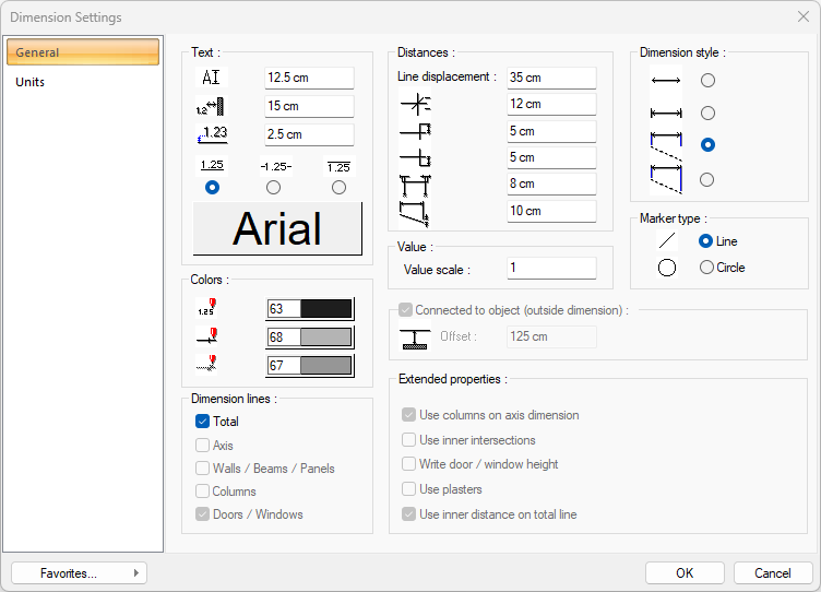
Dimension Settings - General Tab
|
Specifications |
|---|
|
Text Section |
|
The text height of the dimensions is entered. |
|
The distance of the dimension texts from the objects is entered. |
|
The distance of the dimension texts from the dimension line is entered. |
|
The position of the dimension texts according to the dimension line is selected. |
|
When the button is clicked, the “Font Settings” dialog appears. Here you can set the font of the info text. |
|
Distances Section |
|
Line displacement The distance between the dimension lines is determined. |
|
In the dimension lines, the size of the cross braces is entered. |
|
Enter the upper separator size of the dimension line. |
|
The lower separator size of the dimension line is entered. |
|
Enter how long the dimension line will continue after the left and right end reference points. |
|
The distance of the dimension line from the curved objects that the lower separator takes as a reference is entered. |
|
Dimension style 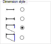
Display type of dimension lines is selected. |
|
Colors Section |
|
Sets the color of the dimension texts. When the color box is clicked, the appropriate color is selected from the pop-up window. |
|
Sets the color of the dimension lines. When the color box is clicked, the appropriate color is selected from the pop-up window. |
|
Sets the color of the dimension markers. When the color box is clicked, the appropriate color is selected from the pop-up window. |
|
Value scale The actual length values written on the dimension line are multiplied with the value written here and the value found as a result of the multiplication is used as the measurement value. For example, dimension line values are 120, 200, 350. If 2 is written to the scale value, the lengths 120, 200, 250 will be written as 240, 400, 700 on the dimension line. |
|
Marker type 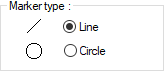
One of the two marker types that can be used in dimension is selected. |
|
Dimension Lines Section |
|
Total Returns the total length of all lines. |
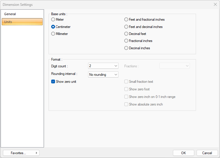
Dimension Settings - Units Tab
|
Specifications |
|---|
|
Basic units 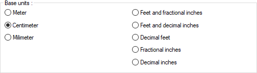
One of the selections is activated by clicking the left mouse button on the job. Meter : If checked, the unit of information text will be meters.
|
|
Digit count 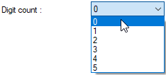
It determines how many digits will be shown after the comma. The desired number is selected from the list. For example, if 2 is selected, units will be shown as two digits after the comma. If 0 is selected, units will not be shown after the comma. |
|
Fractions 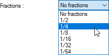
It determines the precision of the dimension to be made in fractional inch format. In the list, there are options with a sensitivity of 1/2, ¼, 1/8, 1/16, 1/32, 1/34. If "no fraction" is selected, units will appear without fractions. |
|
Rounding interval 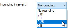
It determines the rounding range of the measurement to be made in meters, centimeters or millimeters. If No rounding is selected, the dimensioning is done at exact value. As the range gets larger, the dimensioning is rounded up to the selected range. |
|
Show zero unit If it is not checked, it does not show the zero and point on the left in dimensioning. For example, it measures 0.20 as 20. If marked, the value 0.20 is scaled as 0.20. |
|
Small fraction text When fractional inch format is selected, determines the fractional part to display in upper / lower case. If it is checked, the fraction is slightly above the integer and small, if not, the fraction is shown the same size next to the integer. |
|
Show zero foot Determines whether 0 is displayed in the 0-foot gauge (less than 1 foot gauge). For example, if it is not checked, it will show a measure of 0 '- 15 "as -15". If marked, it shows as 0'-15 ". |
|
Show zero inch on 0-1 inch range For example, a dimension inch with a value of 8'-0 1/6 "is in the range 0-1. If the option is not ticked, the value 8'-0 1/6" will be displayed as 8'-. In other words, inch values in the 0-1 range will not be displayed. |
|
Show absolute zero inch Determines whether to show zero inches in the dimension value where inches is absolute zero. For example, a dimension of exactly 10 'will be displayed as 10'-0 "if this option is selected. If not checked, it will be displayed as 10" -. |
Usage Steps
-
Enter the section dimension command.
-
Create the first point of the section dimension line by clicking the left mouse button.
-
End your section dimension line by clicking the left mouse button at the point where the dimensioning will end.
-
The section dimension will be created automatically.
|
Usage step |
|---|
|
Creating the first point of the section dimension line 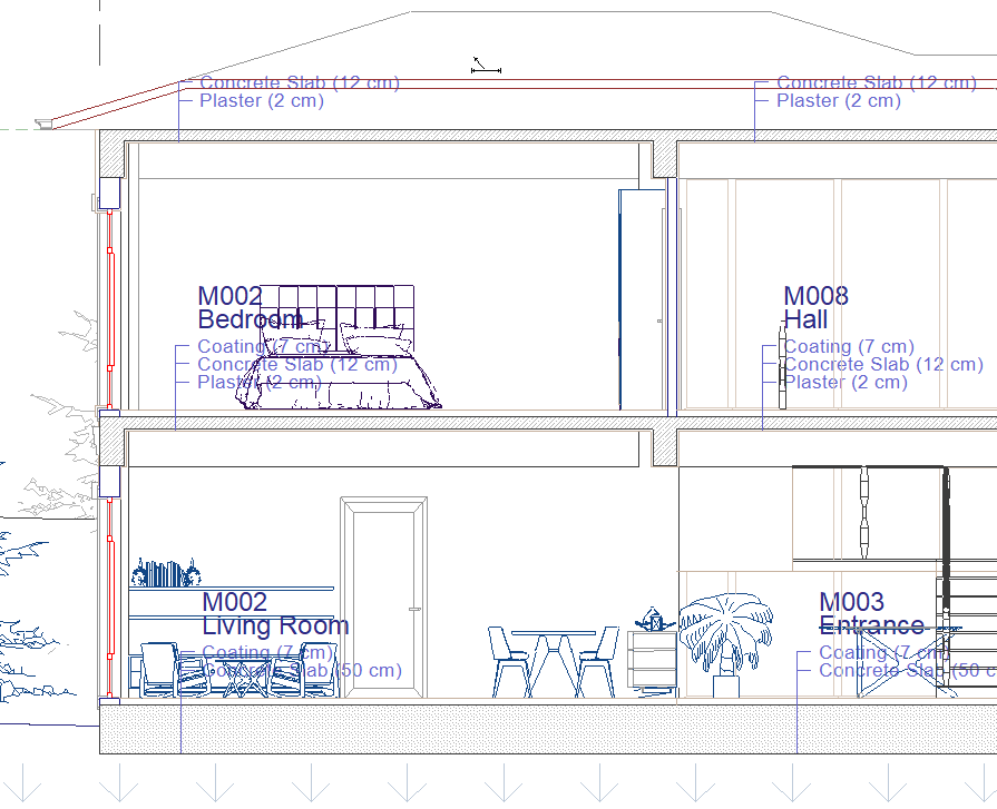
|
|
Creating the end point of the section dimension line 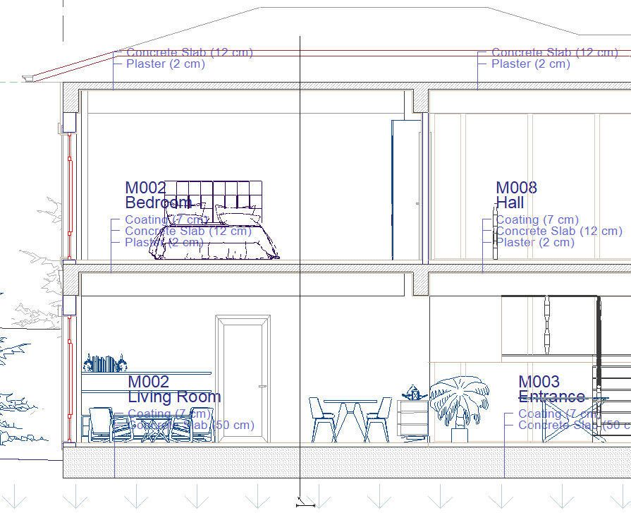
|
|
Formation of the section dimension 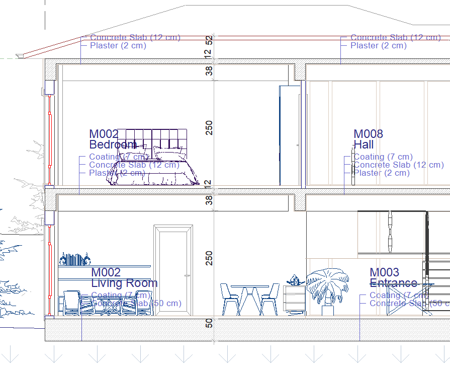
|
Next Topic