
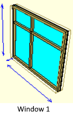
Window 1 is created by following the steps below.
Planning on Paper
Before making a window or door, it would be helpful to plan it on paper. In this way, while the sizing process becomes easier, the possibility of making mistakes will be reduced.
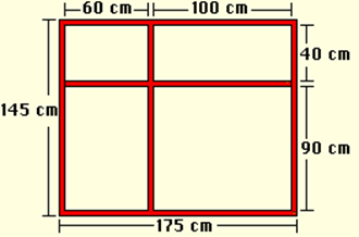
In the above design, the lengths specified in pieces (such as 60,100) only indicate the length of the glass. The widths of the records are considered as 5 cm. Briefly defining the upper edge; 5cm Case Edge - 60cm Glass 1 - 5cm Separator - 100cm Glass Designed as 2 - 5cm Case Edge.
Dio Design Settings
In this step, we will determine our working area before starting the design. This process will allow you to control the size of your window or door during design.
Adjusting the Height of Dio Design
-
Click the Settings / Design DIO Adjust Height line.
-
As soon as you click, your dio design height on the z axis will move with your mouse movement.
-
If you want , you can adjust the height by pressing the Z key and entering a value. When you press the Enter key after entering the value, the design height will be adjusted.
-
If you like the design height of the mouse while moving the lower right corner, depending on the height (Z) control you can adjust by clicking CAE reaches the desired height.
Adjusting the Dio Design Width
-
Click the Settings / Design DIO Set Width row.
-
As soon as you click, your dio design width on the x axis will move with your mouse movement.
-
If you want , you can adjust the width by pressing the X key and entering a value. When you press the Enter key after entering the value, the design width will be adjusted.
Not
You need to make the Dio Design Settings for all DIOs correctly because all Dios are sized with these settings in the ideCAD Architecture. You can also do this process after the window is finished, but it will be useful to finish this process before starting the design in order not to make sizing errors during the design.
Drawing a Square Box
-
Click the Line Drawing / Rectangular Case-Wing .
-
Click your first point at any point in the Front window. The rectangular case / wing will be formed and will start to change shape depending on the mouse. The definition points of the rectangular case / wing must be points on two opposite corners.
-
Create the rectangular case / wing by clicking your second point.
-
Enter the vault properties you have created and select the Empty option in the types section .
Setting the Profile
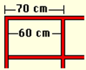
For the window to be created, record widths are designed as 5 cm and thicknesses as 6 cm. Profile dimensions to be selected will be 5/6 cm. Therefore, let's first define a profile with a width of 5 cm and a thickness of 6 cm.
-
Click on the Construction / Profile Editor row.
-
Enter 0.01 for the X / Y values in the grid section. These values represent the distances of the jump points on the grid from each other.
-
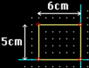
Click the New button in the lower right corner . Enter a name for the profile you want to create. You will see a profile of x = 6 cm y = 6 cm.
-
In the grid section, check the Lock to grid option, so you will be able to resize as whole numbers.
-
Changes you make in the Y axis in the profile will be reflected in the width of the frame edges and the thickness of the changes you make in the X axis.
-
The designed case edge thickness will be 6 cm and the width will be 5 cm. In this case, the frame can be created as designed by shortening the height of the profile by 1 cm and obtaining a profile with the dimensions x = 6, y = 5 cm. To do this, click the point in the upper right corner and move it to a lower point in the grid. Do the same with the dot in the upper left corner.
-
We need to move the origin point of this profile to the lower right corner in order to ensure that the frame edges extend from the nodes and form within the design boundaries.
-
Click the Set origin point icon.
-
Click the bottom right node of the profile
-
Click the OK button. Against your Changed Under Profile for whether to register? message will come. Click on the Yes button.
Assigning Profile to Vault
-
Click the Properties line from the list that opens when you point to the safe and click the right mouse button .
-
The Case / Wing dialog will be displayed. Select the name of the profile you created from the Profile row in the parameters section in the middle .
-
When you click the OK button, the profile you selected will be assigned to the safe.
Drawing the Separators
-
Click on the Line Drawing / Separator .
-
Click the first point of the vertical separator. This point will be at coordinates X = 0.7, Z = 0.05.
-
The end point will be at coordinates X = 0.7, Z = 1.4 (you can do it in 1.45, but in this case, the separator will intersect with the casing edge and create an undesirable image).
-
Click the Properties line from the list that appears when you hover over the separator and click the right mouse button .
-
The separator dialog will be displayed. Select the name of the profile you created from the Profile row in the parameters section in the middle .
-
When you click the OK button, the profile you selected will be assigned to the separator.
-
Draw the horizontal divider in the same way.

Glass Identification
To create the window glass;
-
Click the Jump to Support / Object Points row and select the crates and separators. The node points will appear.
-
Click the Line Drawing / Polygon .
-
Draw your polygon and glass boundaries with reference to the case inner nodes.
-
Click the Change / Extend line and select the polygon.
-
Enter x = 0, y = 0.02, z = 0.0 values from the dialog box that appears (You can do the extension by moving the extended part with the mouse, but it will be useful to enter values from the dialog box to ensure that the values are integers.).
-
Your object will be created.
Drawing the Void Polygon
-
Click on the Line Drawing / Gap Polygon .
-
Go around your case with the space polygon, referring to the outer nodes of the case.
-
The gap polygon will close when you connect the last point with the first point.
Creating Material and Covering the Window with This Material
-
Click on the Construction / Add New Material row.
-
In the dialog that comes up, click and hold the Color box and select the appropriate color.
-
If you activate the Transparent option, all objects covered with that material will be included in the ideCAD Architectural program transparently during rendering.
-
Name your material.
-
Click the Add button. The material will become active in the materials section at the bottom of the design tracking window.
-
Enter the Properties of the vault . Select the material you created in the Material section from the Parameters section .
-
Do the item assignment for all elements of the window.
Creating Plan, Section and View Drawings
In order for the created window to appear on the plan, section, and view pages, these must be created before the dio is saved.
-
You can create your plan automatically by clicking on the Construction / Create Plan line.
-
You can automatically create your cross section by clicking on the Construct / Create Section line.
-
You can create your view automatically by clicking on the Construction / Create Appearance line.
Later, you can make any changes you want in 2 dimensions in plan, section and views and detail them.
Next Topic