
ICONS
A c = Gross cross-section area of the column or wall end region
A ck = Core concrete area within the measure taken outside the outer of the confinement reinforcement
A sh = s along the height corresponding to the transverse reinforcement range, taking into account the cross-sectional area values of all hoops and crossties in the column or the sum of the projections in the perpendicular direction
b k = Cross-section dimension of the column or wall end zone core (distance between the outermost transverse reinforcement axes) for each of the perpendicular horizontal directions
b w =Width of the column in the direction of transverse reinforcement calculation
f ck = Characteristic cylinder compressive strength of concrete
f ctd = Design tensile strength of concrete
f ywk = Characteristic yield strength of transverse reinforcement
N d = Axial force calculated under the combined effect of vertical loads and earthquake loads multiplied by load coefficients
s = Transverse reinforcement spacing, spiral / wrapping reinforcement pitch
ρ = reinforcement ratio
ρ s = volumetric ratio of spiral reinforcement in the column
ϕ = Diameter of reinforcement
7.3.4. Transverse Reinforcement Conditions
Unless a more unfavorable situation is obtained than in 7.3.7.6 , the conditions for the minimum transverse reinforcement to be used in columns are given in 7.3.4.1 for the column confinement zones and in 7.3.4.2 for the column middle zone ( Figure 7.3 ). Special seismic hoops and special seismic crossties defined in 7.2.8 will be used along the entire column .
7.3.4.1 - Special confinement zones will be created at the lower and upper ends of each column . The length of each of the confinement zones is less than 1/6 of the column free height, 1.5 times the largest section size of the column, and 500 mm, measured from the top of the slab upwards or downwards from the bottom face of the largest beam. will not be. In cantilever columns, the confinement zone will be formed at the lower end of the column and its length will not be smaller than twice the size of the column. Conditions for transverse reinforcement to be used in confinement zones are (a) to (d) below .It is given in. These reinforcements will be continued in the foundation along a height not less than the minimum dimension of the column. However, transverse reinforcement in the confinement area will be continued along the height of the bowl in the columns that are supported to the bowl foundations.
(a) Transverse reinforcement with a diameter less than ϕ8 shall not be used in confinement zones. In this region , the stirrups and crossties spacing in the longitudinal direction shall not be larger than 1/3 of the smallest section size, 150 mm larger, six times the longitudinal reinforcement diameter, and less than 50 mm. The horizontal distance between the stirrup arms and / or crossties, a , shall not be taken larger than 25 times the stirrup diameter. The pitch of continuous circular spirals shall not be greater than 1/5 of the core diameter and 80 mm. In circular columns, all wrapping reinforcement will be provided with circumferential transverse reinforcement placed around the perimeter.
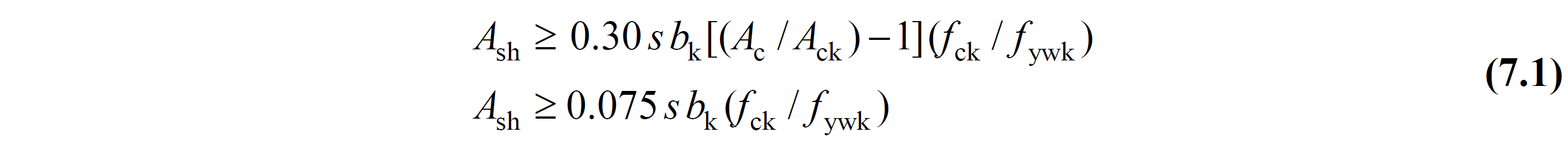
(b) In case of N d > 0.20 A c f ck (pressure ) in stirruped columns, the minimum total transverse reinforcement area in the confinement zones shall be calculated in such a way that the conditions given in Equation (7.1) are unfavorable. In this calculation, the core size b k of the column will be considered separately for both directions ( Figure 7.3 ):
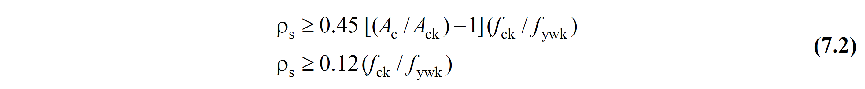
(c) In case of N d > 0.20 A c f ck (pressure ) in circular reinforced columns , the minimum volumetric ratio of the transverse reinforcement in the confinement zones shall be calculated in a way that the conditions in Equation (7.2) are unfavorable.
(d) In case of N d ≤ 0.20 A c f ck , at least 2/3 of the transverse reinforcement given in Equation (7.1) and Equation (7.2) will be used as minimum transverse reinforcement in the column confinement regions .
7.3.4.2 - The middle zone of the column is the zone between the confinement zones defined at the lower and upper ends of the column ( Figure 7.3 ). Transverse reinforcement with a diameter smaller than ϕ8 shall not be used in the middle of the column. Stirrup, crossover or spiral spacing along the column shall not be taken larger than half of the smallest cross-section size and 200 mm. The horizontal distance between the stirrup arms and / or crossties, a , shall not be more than 25 times the stirrup diameter.