
-
Constant or Adaptive Single Mode Pushover Analysis Method selection is at user control.
-
According to the chosen pushover analysis method, plastic deformations, deformation limits and building performance are calculated automatically.
-
The applicability of single mode pushover analysis methods is automatically checked.
ICONS
η bi = Torsional Irregularity Coefficient defined on the i th floor
Single Mode Pushover Analysis Methods are the non-linear incremental counterpart of the single-mode implementation of the linear Modal Response Spectrum Analysis described in Chapter 4 of TDY . Therefore , modal structural equivalents such as calculated mode shapes, modal contribution factor, modal effective mass used in Mode Combination Method are used in Single Mode Pushover Analysis Methods .
According to TDY 5.6.2.2 , both conditions (a) and (b) defined below must be met in order for the Single Mode Pushover Analysis Methods to be applied :
(a) Any additional eccentricity floor based on the consideration of the linear elastic behavior TDY Table 3.5 'e calculated by torsional irregularity coefficient 's η b is <1.4 to provide the required condition.
(b) In the earthquake direction considered, the ratio of the effective mass of the base shear force of the dominant vibration mode calculated on the basis of the linear elastic behavior to the total building mass must be at least 0.7. This rate is also calculated as the Modal Mass Participation Rate . For this reason, the mass participation ratio of the dominant vibration mode should be greater than 0.7 in the direction considered in single-mode propulsion methods.
According to TDY 5.6.2.3 , in Single Mode Pushover Analysis Methods , the displacement, plastic deformation, which occurs in the carrier system under the influence of the earthquake load increments applied step by step monotonically up to the earthquake displacement demand limit , in proportion to the prevailing vibration mode shape in the earthquake direction considered. and internal force increments and their cumulative values are calculated. In the last step, displacement, plastic deformation and internal forces are obtained.
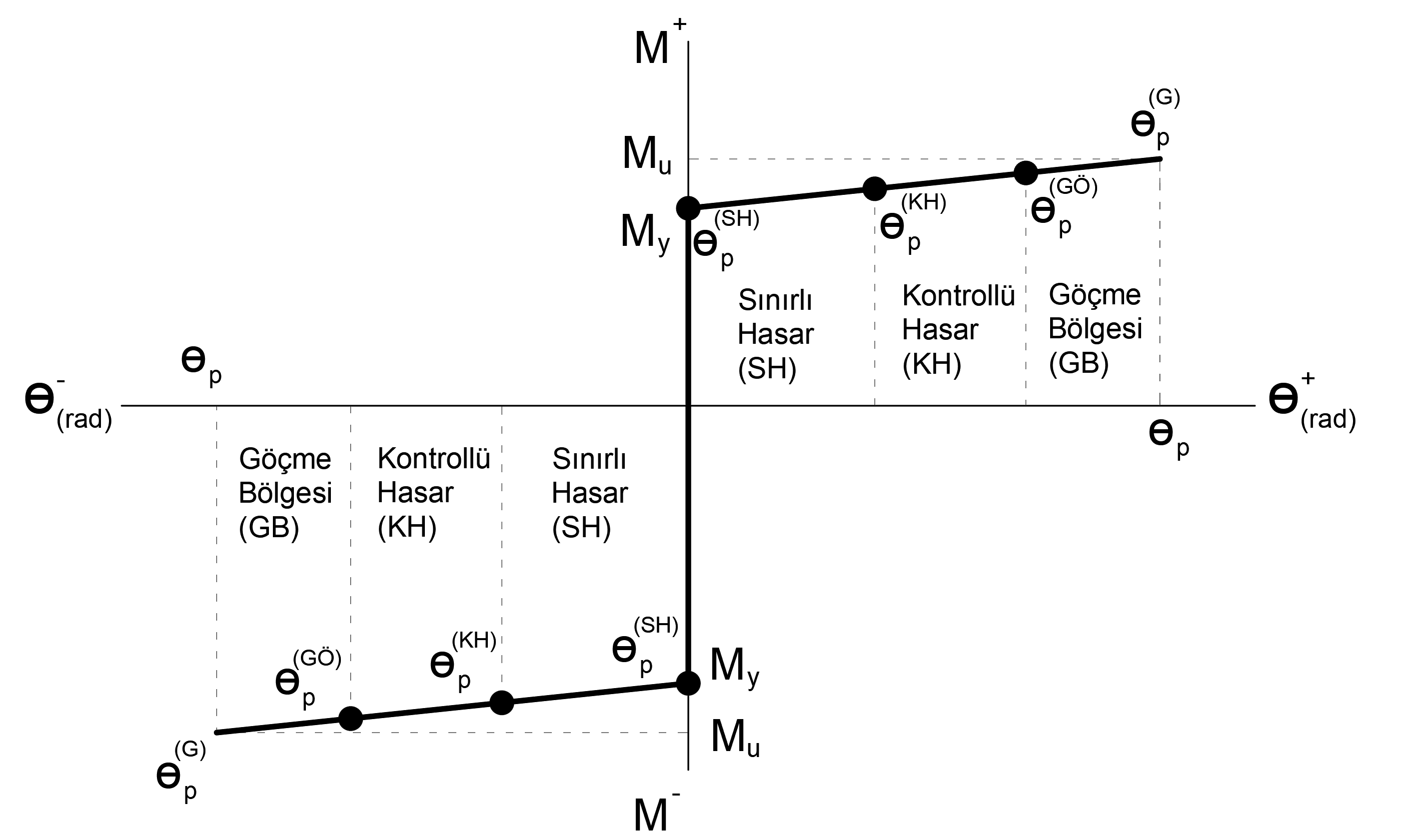
Plastic deformation demands , plastic hinges calculated in performance compared with the plastic rotation element point performance was determined. Similarly , the unit performance is determined by comparing the strain demands of the wall elements with the concrete and reinforcing steel strain values calculated at the performance point using the distributed plastic behavior model .
Two different Single Mode Pushover Analysis Methods are defined in TDY . The Constant Single Mode Pushover Analysis Method specified in TDY 5.6.3 or the Adaptive Single Mode Pushover Analysis Method specified in TDY 5.6.4 may be used.
An example of the plastic joint skeleton curve showing the plastic joint limit values and element performance for new buildings is given below.
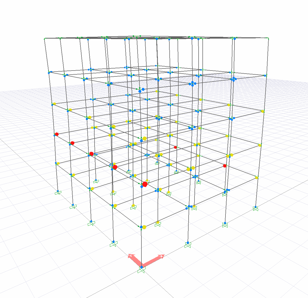
The performance evaluation of plastic hinges can be viewed on the three-dimensional screen.
According to TDY 5.6.2.4 , when the rigid diaphragm assumption is made at each floor and the horizontal components of the degrees of freedom in two perpendicular directions at the floor mass center, it is defined as the rotation around the level axis.
Related Topics