
Symbols
Ag : Gross cross-sectional area of member
Cw : Warping constant, in.6 (mm6)
E: Structural steel modulus of elasticity
Fcr : Critical stress
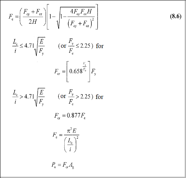
Fe : Elastic buckling stress determined according to Equation 8.6
Fey : Elastic buckling stress in buckling limit state with bending around the y-axis
Fez : Elastic buckling stress in torsional buckling limit state z-axis
Fy : Specified minimum yield stress of the type of steel being used
G: Shear modulus of elasticity of steel = 11,200 ksi (77 200 MPa)
H: Flexural constant
K : Effective length factor
L: Laterally unbraced length of the member
i: Radius of inertia
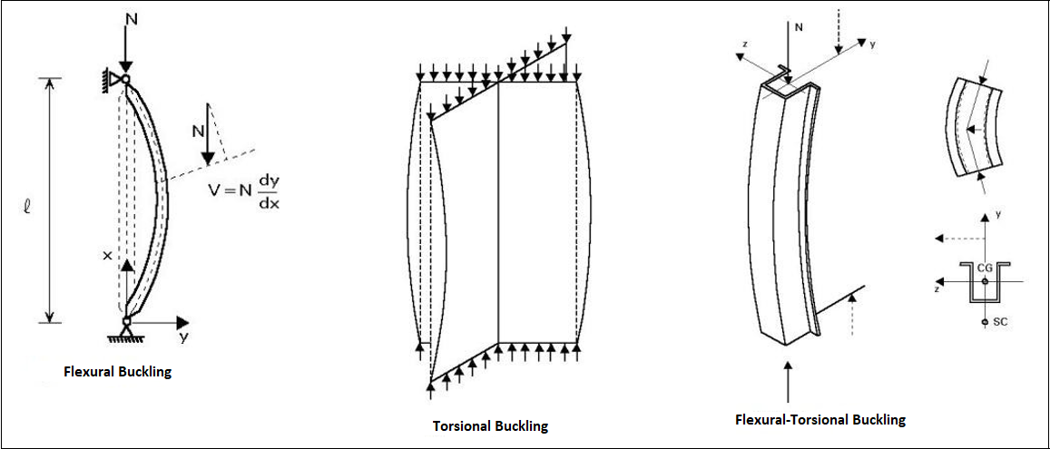
Flexural Torsional Buckling Limit State
-
When symmetry axis is the y-axis, where the buckling around the y-axis is caused by the bending and rotation of the element around its longitudinal axis on the Double-Leg angle, T profile, U profile and Single Equal-Leg angle sections that are under compression around their symmetry axes.
Design with ÇYTHYE 2018
-
The compressive strength of the elements is determined according to the axial force acting into the center of gravity section.
-
With the symmetry axis being the y-axis, the elastic buckling stress Fe in the flexural-torsional buckling limit state where buckling around the y-axis occurs by bending and rotating around the longitudinal axis, Fe is calculated according to equation 8.6.
Next Topic