
In this example, the end displacements of the system consisting of a built-in rod element defined at an angle according to the global axis are examined and compared with the results of ideCAD Structural.
Important Note: In this system solution, the effects of elongation and shear deformations are neglected for ease of manual solution. The cross-sectional area is multiplied by 1000 to neglect the elongation deformations, and the shear areas are defined as zero "0" to ignore the shear deformations.
|
Loading Status |
Compared Value |
ideCAD Static |
Manual solution |
Percentage of error |
|---|---|---|---|---|
|
|
UY (in) |
-0.0181 |
-0.0181 |
0% |
|
UZ (in) |
-0.0303 |
-0.0303 |
0% |
|
|
|
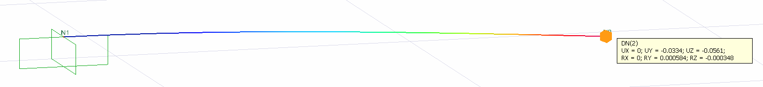
UY (in) |
-0.0334 |
-0.0334 |
0% |
|
UZ (in) |
-0.0561 |
-0.0561 |
0% |
|
|
|
UY (in) |
-0.0836 |
-0.0836 |
0% |
|
UZ (in) |
-0.0140 |
-0.0140 |
0% |
Geometric Properties and System Description
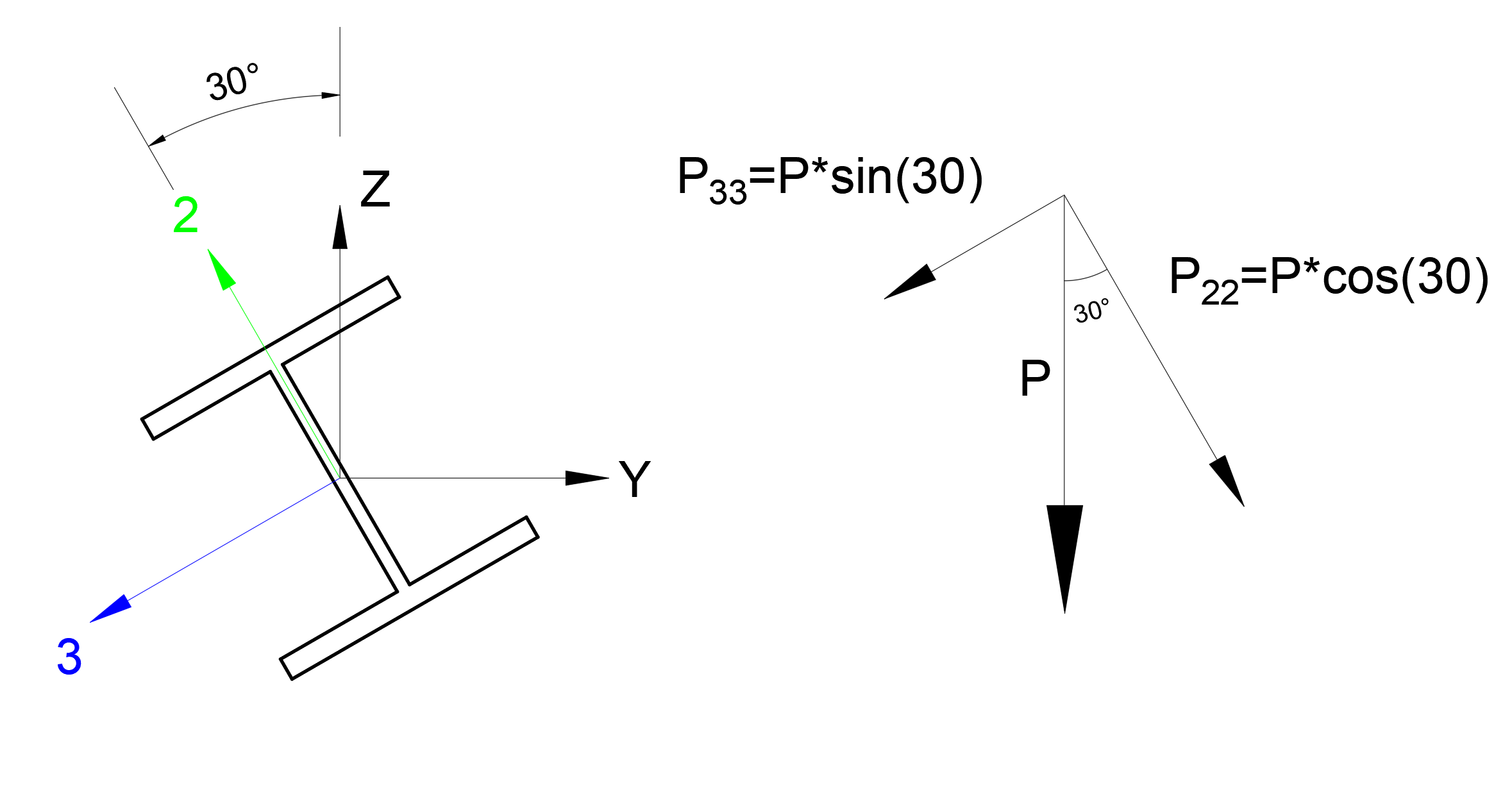
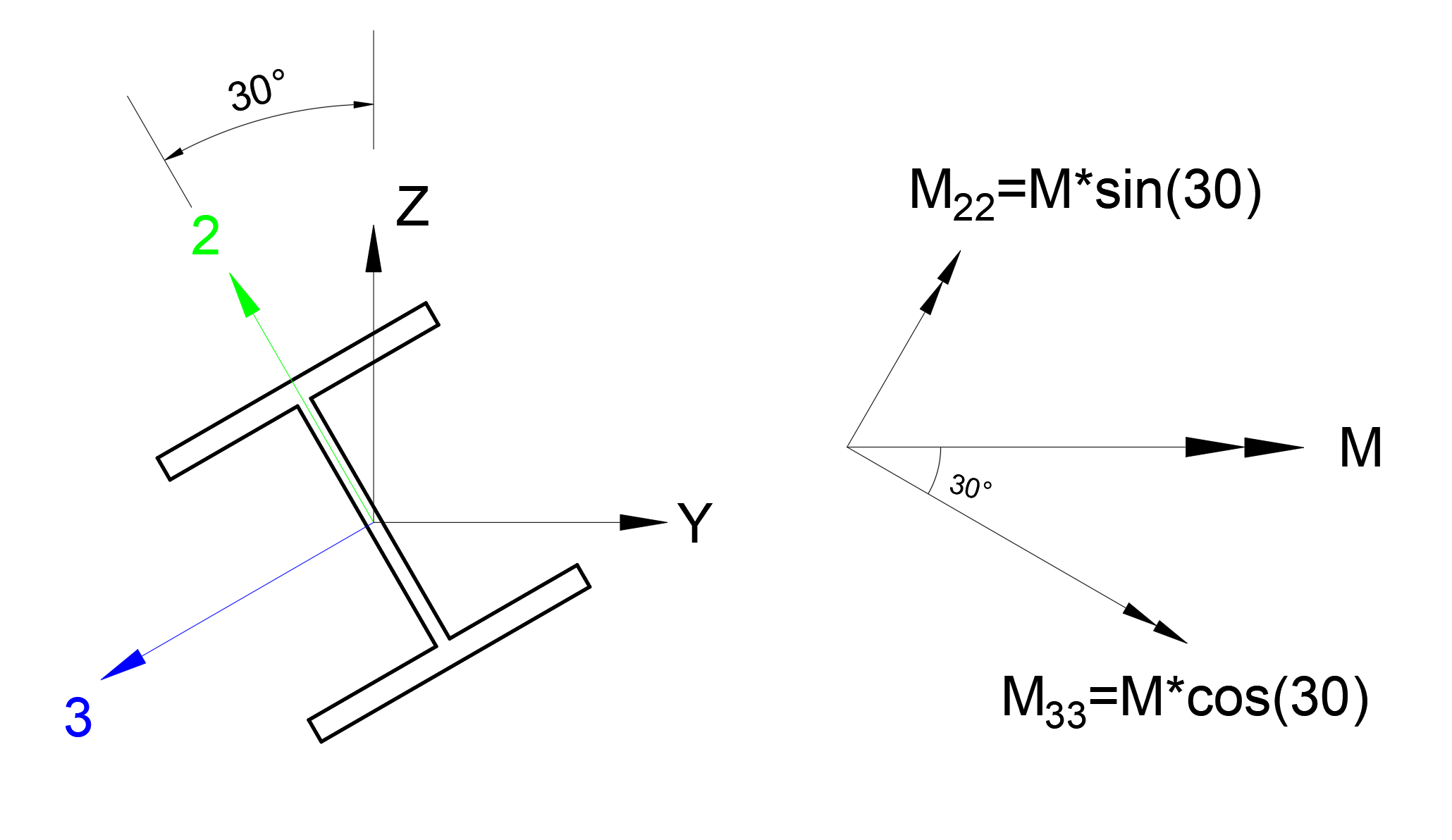
Below about 144 in length, according to the global axis 30 o rotated console shows the system information of a member. Global axes are defined as YZ axes and local axes as 3-2 axes.
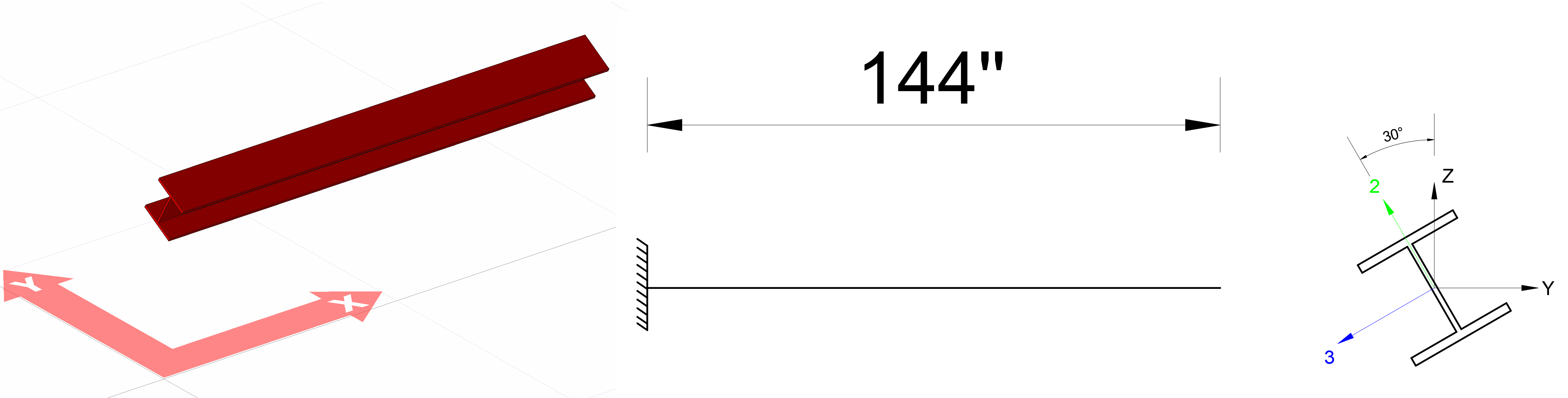
W12x106 profile is used as a rod element. The section height was defined as 12.9 inches, section width 12.2 inches, upper-lower cap thickness 0.99 and body thickness 0.61 inches. In this case;
The moment of inertia in the 3 axis I 3 = 933 in the 4
2 axis is found to be I 2 = 301 in 4
. The elasticity modulus of the steel material used is defined as E = 29000 k / in 2 .
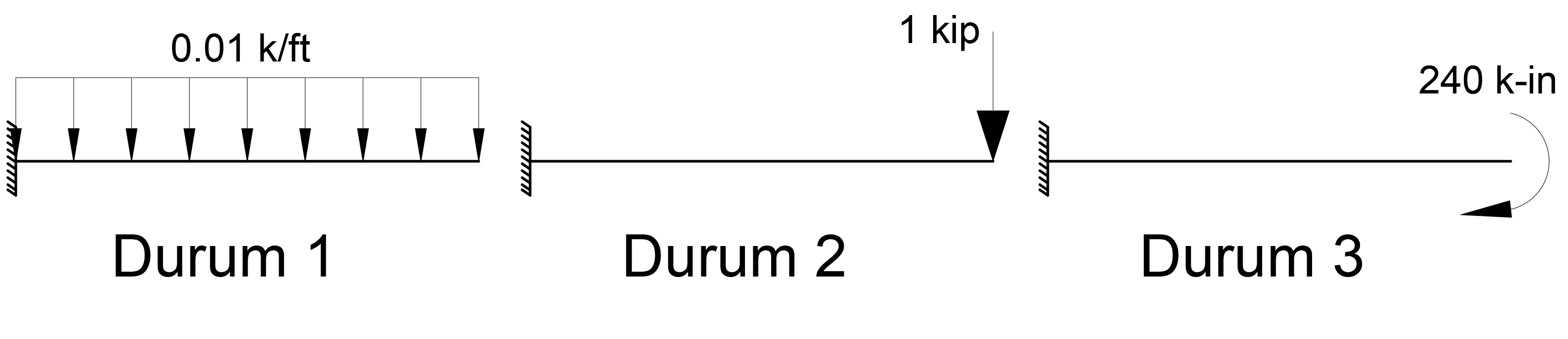
Loading situations
3 loading conditions are defined on the console element whose local axis is defined at an angle of 30o above . In these loading cases called Case 1, Case 2 and Case 3, the displacements in the Y and Z axes at the free ends of the element relative to the global axis will be calculated.
The end displacement of the cantilever element under uniformly distributed loading, the end displacement of the cantilever element under single loading and the end displacement equations of the cantilever element under the effect of singular moment are respectively given below.
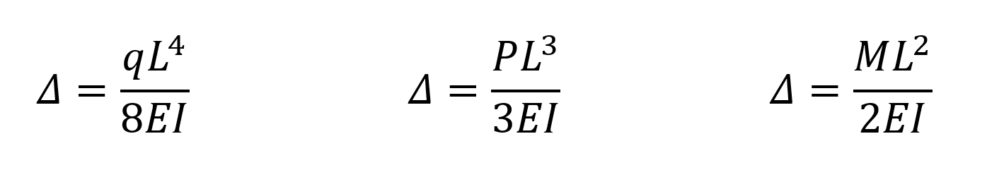
In the above equations, Δ is the end displacement value of the cantilever element, L is the cantilever element length, E is the modulus of elasticity, I is the moment of inertia, q is the uniform load value, P is the individual load value and M is the singular moment value. The above equations can be used for Case 1, Case 2 and Case 3. However, since the cantilever element is defined as an angle and the load values are defined to global axes, the above equations should be calculated by using the relevant moments of inertia in both the Y and Z axes.
You can reach the file with all loading statuses defined below.
Lokal Ekseni Açılı Çubuk Örneği.rar
Condition 1
The distributed loading state is defined as q = -0.01 k / ft with respect to the global Z axis. In this case, the component of the distributed load case q on the 3 axis (local axis) of the element will be q 33 = q * sin (30). Similarly, the component of the distributed load case q on the 2 axis (local axis) of the apple will be q 22 = q * cos (30).
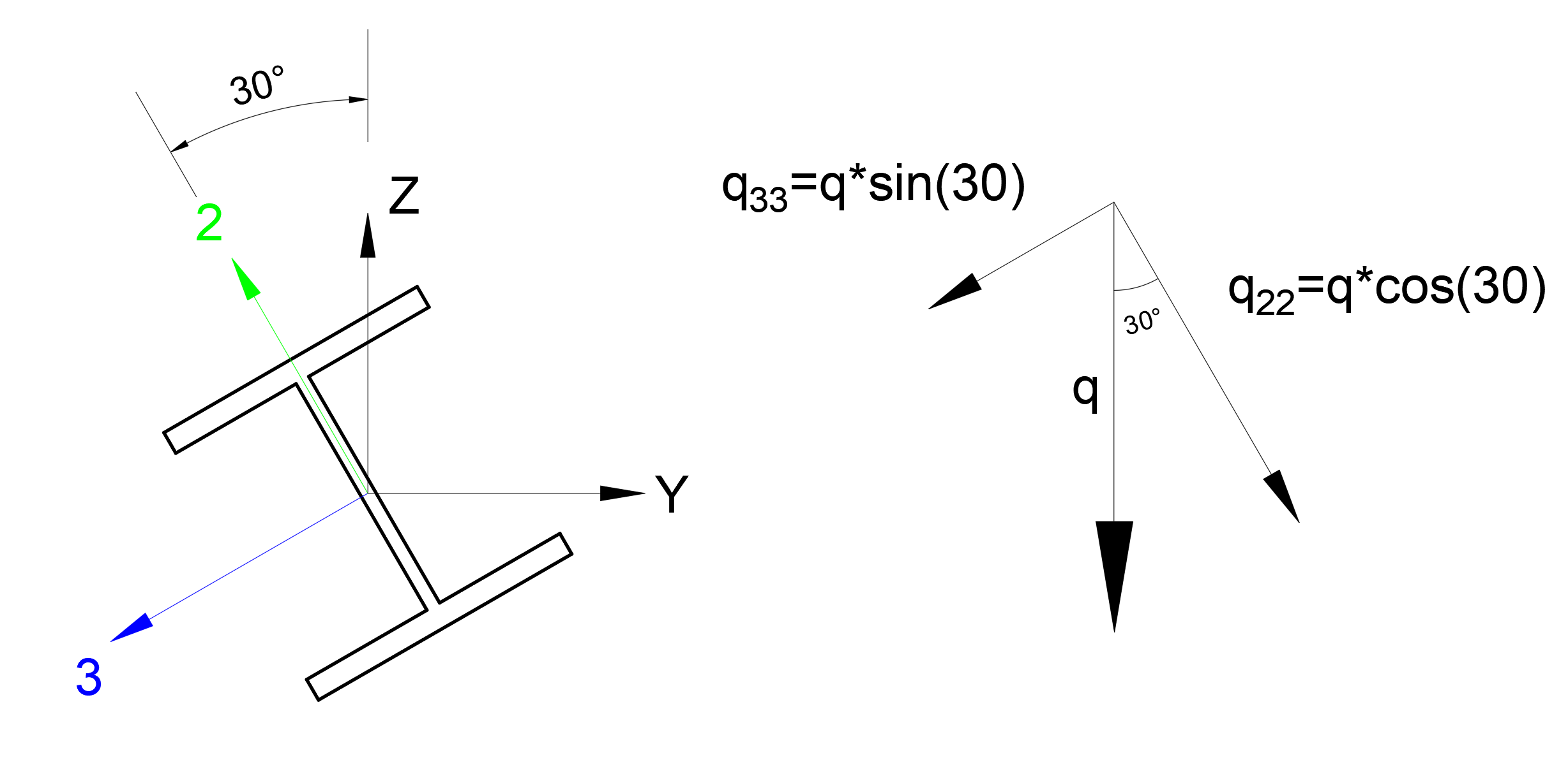
The calculation of the uç value of the end displacement of the cantilever element under uniformly distributed loading according to the local axes of the element is as follows.
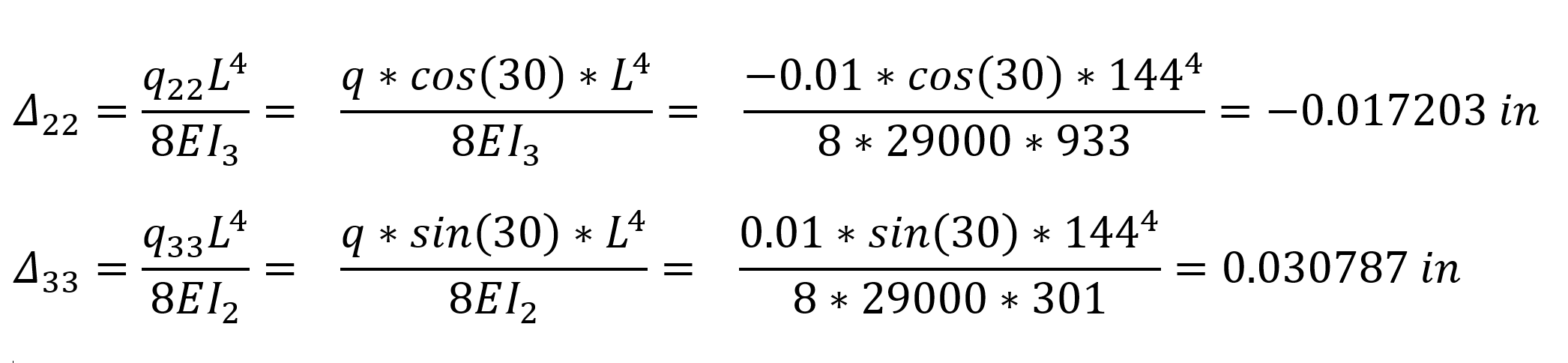
In the above relations, Δ 22 is the displacement of the element in the 2 direction relative to the local axis, Δ 33 is the displacement of the element in the 3 direction with respect to the local axis. The following operations can be applied to convert these values to global axes.
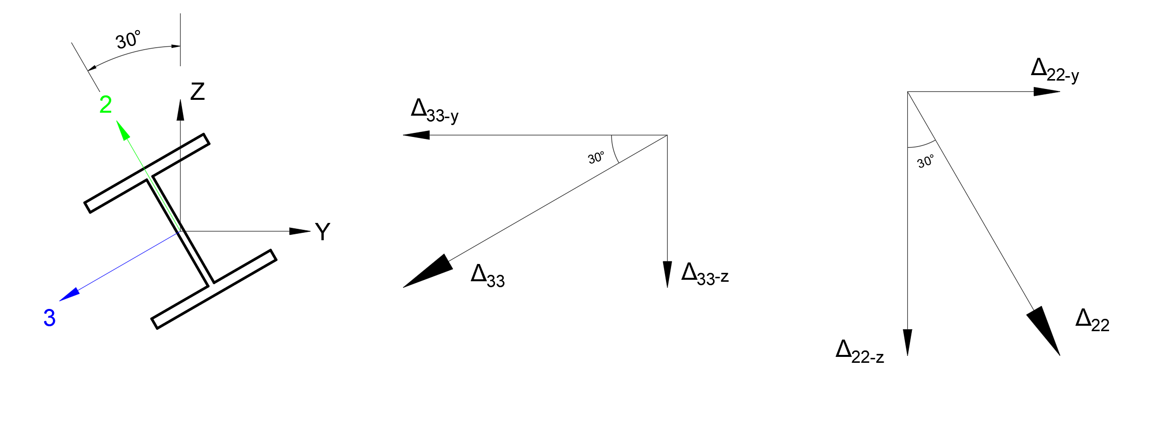
Δ The projection of the 33 displacements on the z global axis Δ 33-z = 0.030787 * sin (30) = 0.015393 in
The projection of the 33 displacement on the y global axis Δ 33-y = 0.030787 * cos (30) = 0.026662 in
The projection of the 22 displacement on the z global axis Δ 22-z = 0.017203 * cos (30) = 0.014898 in
The projection of the 22 displacement on the y global axis Δ 22-y = 0.017203 * sin (30) = 0.008602 in
found as. When these displacement values are summed by considering the directions of loading;
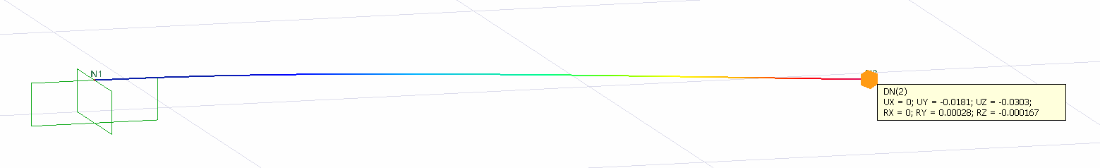
ΔY = 0.008602 - 0.026662 = -0.0181 in
Δz = -0.015393 - 0.014898 = -0.0303 in
found as.
The values of Δ Y = -0.0181 and Δ z = -0.0303 are exactly the same as the results of ideCAD Structural.
Condition 2
The single load case is defined as P = 1 mode with respect to the global Z axis. In this case, P 33 = P * sin (30), the component of the P single loading case in the 3 axis (local axis) of the element . Similarly, the component of the P singular loading case in the 2 axes (local axis) of the apple will be P 22 = P * cos (30).
The calculation of the end displacement Δ of the cantilever element with respect to the local axes of the element is as follows.
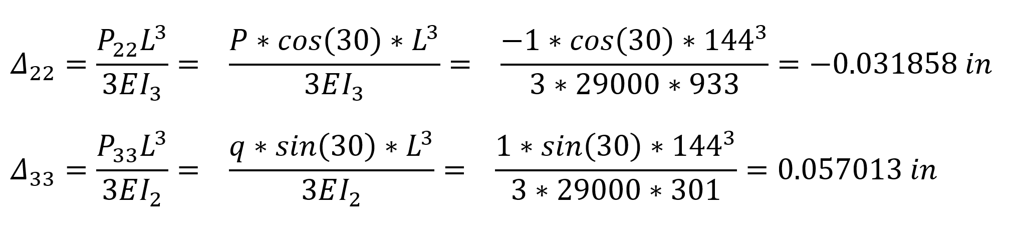
In the above relations, Δ 22 is the displacement of the element in the 2 direction relative to the local axis, Δ 33 is the displacement of the element in the 3 direction with respect to the local axis. The following operations can be applied to convert these values to global axes.
Δ The projection of 33 displacements on the z global axis Δ 33-z = 0.057013 * sin (30) = 0.028506 in
The projection of the 33 displacement on the y global axis Δ 33-y = 0.057013 * cos (30) = 0.049375 in
The projection of the 22 displacement on the z global axis Δ 22-z = 0.031858 * cos (30) = 0.027590 in
The projection of the displacement of 22 on the y global axis Δ 22-y = 0.031858 * sin (30) = 0.015929 in
found as. When these displacement values are summed by considering the directions of loading;
ΔY = 0.015929 - 0.049374 = - 0.0334 in
Δz = -0.027590 - 0.028506 = - 0.0561 in
found as.
The values of Δ Y = -0.0334 and Δ z = -0.0561 are exactly the same as the results of ideCAD Structural.
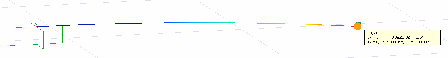
Condition 3
The singular moment load case is defined as M = 240 k-in around the global Y axis. In this case, the component of the M single moment loading situation around the 3 axis (local axis) of the element will be M 33 = M * cos (30). Similarly, the component of the M singular moment loading situation around the 2 axis of the apple (local axis) will be M 22 = M * cos (30).
The calculation of the end displacement Δ of the cantilever element under the effect of the individual moment loading according to the local axes of the element is as follows.
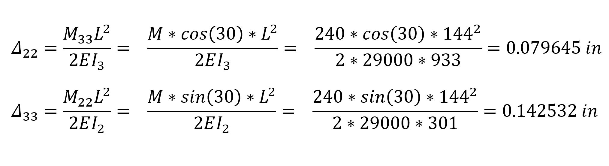
In the above relations, Δ 22 is the displacement of the element in the 2 direction relative to the local axis, Δ 33 is the displacement of the element in the 3 direction with respect to the local axis. The following operations can be applied to convert these values to global axes.
Δ The projection of the 33 displacements on the z global axis Δ 33-z = 0.142532 * sin (30) = 0.071266 in
The projection of the 33 displacement on the y global axis Δ 33-y = 0.142532 * cos (30) = 0.123436 in
The projection of the 22 displacement on the z global axis Δ 22-z = 0.079645 * cos (30) = 0.068974 in
The projection of the 22 displacement on the y global axis Δ 22-y = 0.079645 * sin (30) = 0.039822 in
found as. When these displacement values are summed by considering the directions of loading;
ΔY = 0.039822 - 0.123436 = - 0.0836 in
Δz = -0.068974 - 0.071266 = - 0.0140 in
found as.
The values of Δ Y = -0.0836 and Δ z = -0.0140 are exactly the same as the results of ideCAD Structural.
Next Topic