
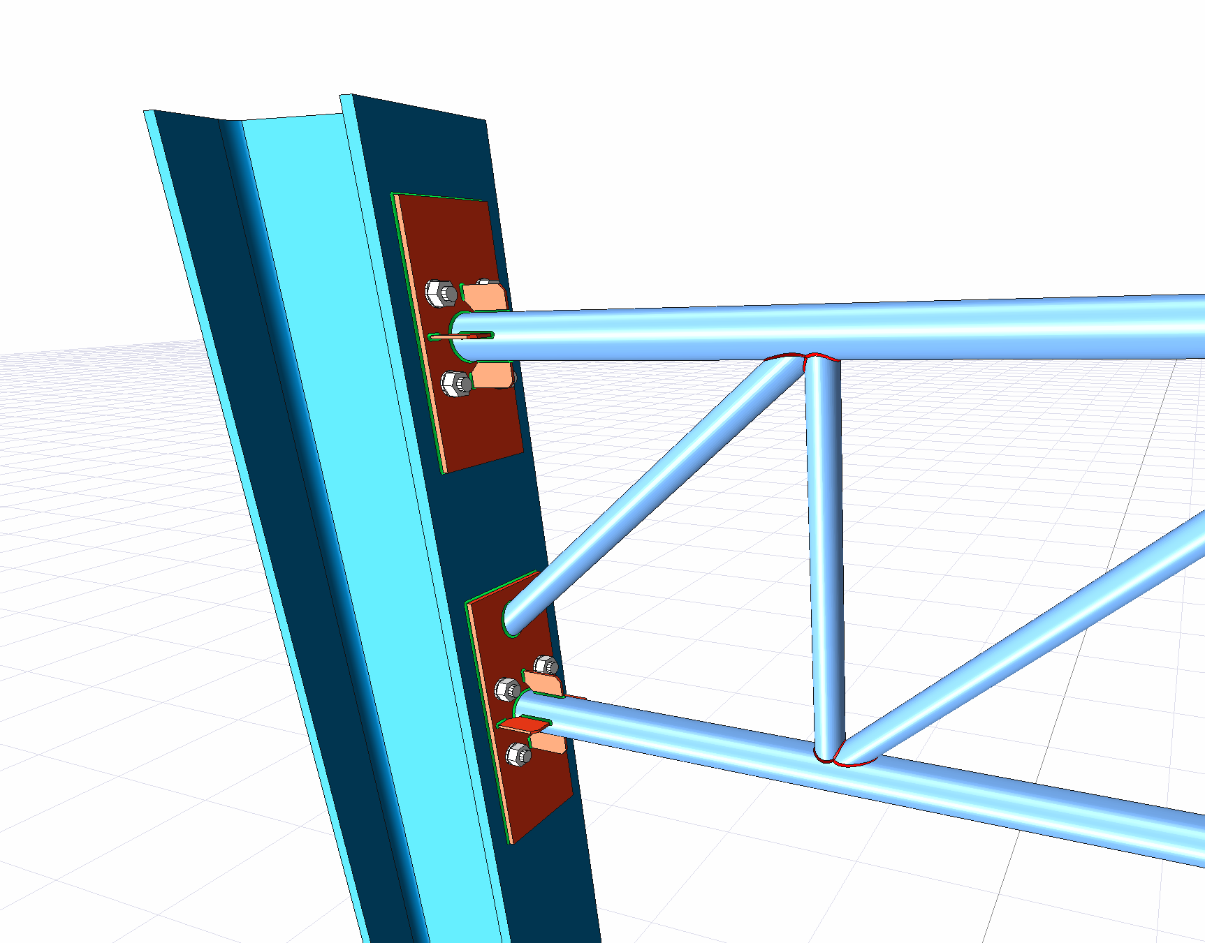
With the End Plate Truss Connection for Box/Tube command, column-truss connection is defined.
Location of End Plate Truss Connection for Box/Tube Command
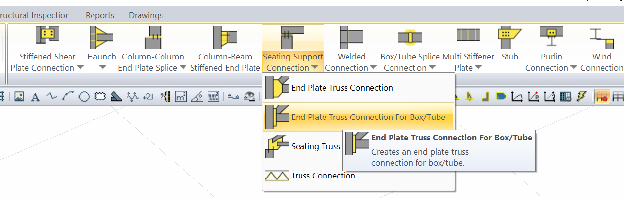
You can access it under the Ribbon menu Joint tab under the Constructive Joints heading.
Usage Steps
After drawing and adjusting Trusses consisting of box and pipe profiles
-
From the Support Zone Join list, click the Butt Plate Shear Joint line for Box and Pipe Profiles.
-
Select the main element (column) and click the right mouse button.
-
Select the scissor elements that connect to the main element and click the right mouse button.
-
The merge will occur with the default settings.
Location of the End Plate Truss Connection Settings Dialog
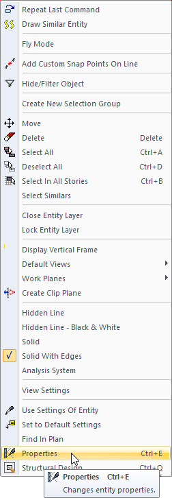
Select the resulting combination and click the right mouse button. Click Properties from the right-click menu that opens.
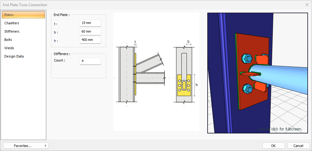
End Plate Truss Connection Dialogue for Box/Tube Profiles
Plates Tab
|
Specifications |
|---|
|
End Plate 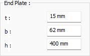
The face plate is determined by entering the value. The values to be entered are shown in the schematic drawing. |
|
Schematic drawing 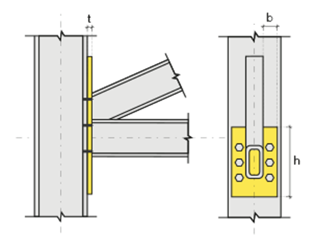
Joint and plate values are shown on the schematic drawing. |
|
Preview 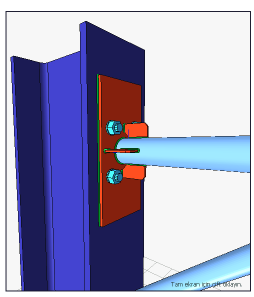
Includes a preview of the merge. The selection made and the entered values can be followed simultaneously in the preview. |
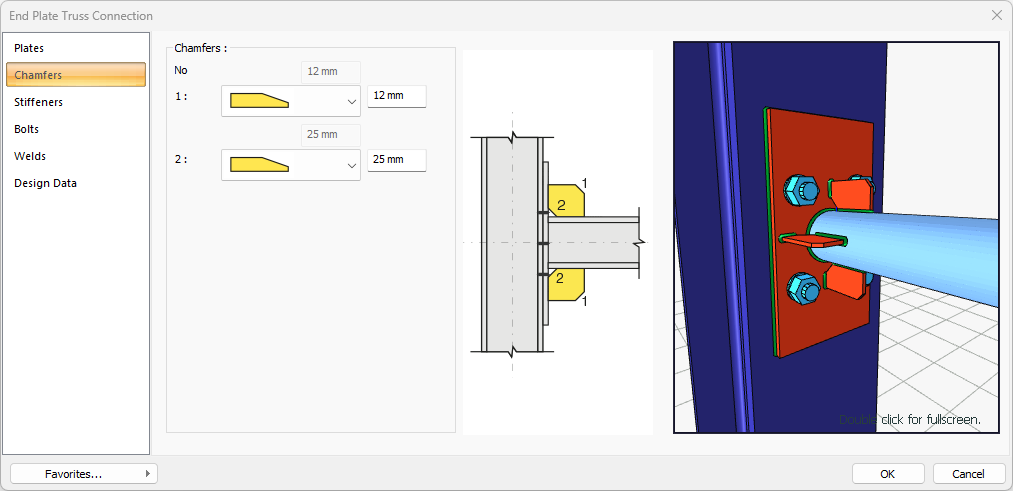
Chamfers Tab
|
Specifications |
|---|
|
Chamfers 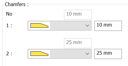
For easy installation of the boards in the field, the use of the slope, the slope type and geometric properties are determined by entering the value. |
|
Schematic drawing 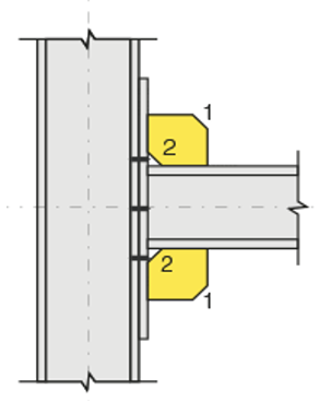
Joint and plate values are shown on the schematic drawing. |
|
Preview
Includes a preview of the merge. The selection made and the entered values can be followed simultaneously in the preview. |
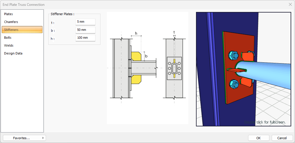
Stiffners Tab
|
Specifications |
|---|
|
Reinforcement Plates 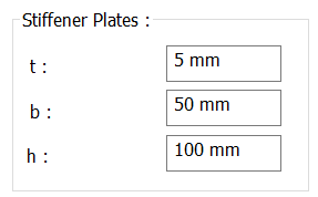
Plate dimensions are determined by entering values. The values to be entered are shown in the schematic drawing. |
|
Schematic drawing 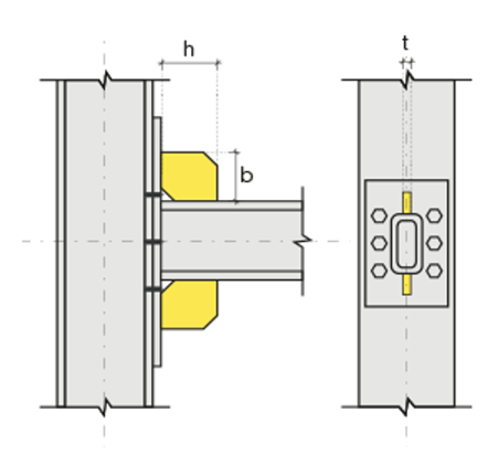
Joint and plate values are shown on the schematic drawing. |
|
Preview
Includes a preview of the merge. The selection made and the entered values can be followed simultaneously in the preview. |
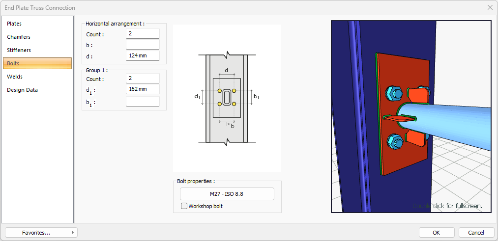
Bolts Tab
|
Specifications |
|---|
|
Horizontal Arrangement 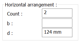
The horizontal placement distance value of the bolts is entered. The values to be entered are shown in the schematic drawing. |
|
Group 1 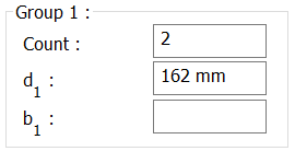
Distance values are entered for the bolts to the beam and other bolts. The values to be entered are shown in the schematic drawing. |
|
Bolt Properties 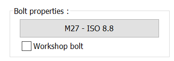
By clicking the Bolt Properties button, the Hole and Bolt Parameters dialog is opened. Bolt properties are set from this dialog. |
|
Schematic drawing 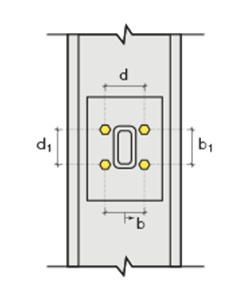
Joint and bolt placement values are shown on the schematic drawing. |
|
Preview
Includes a preview of the merge. The selection made and the entered values can be followed simultaneously in the forecast. |
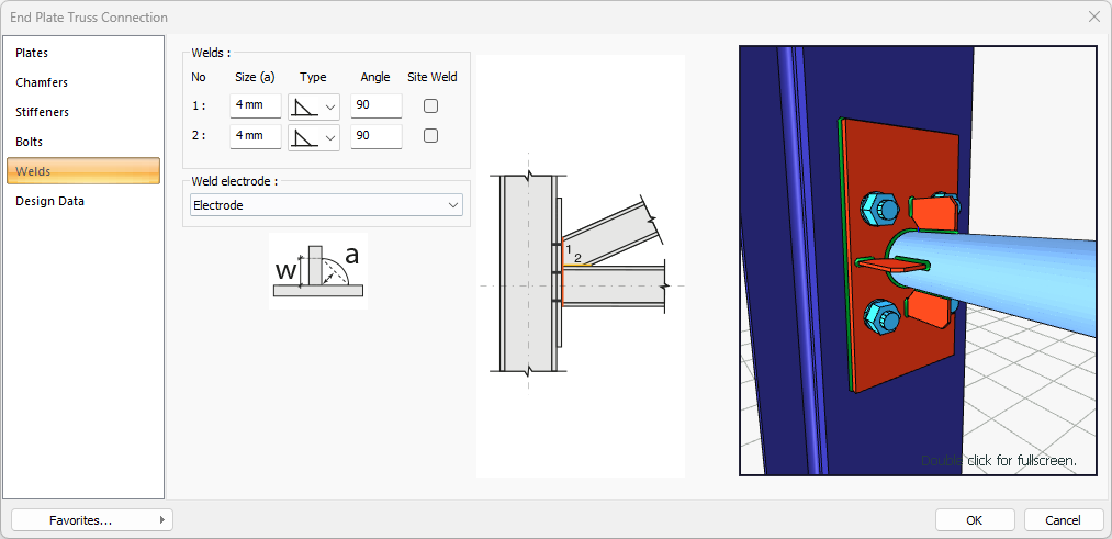
Welds Tab
|
Specifications |
|---|
|
Welds 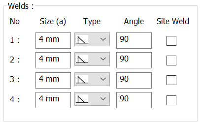
The thickness, type and angle values of the welds to be made at the joints are given. Enter the information whether it will be done at the construction site or not. |
|
Weld electrode The strengths of the welding electrodes are defined in the design inputs. The condition that the main element strength in the weld joint has less strength than the weld strength is checked. To create the welding electrode, give the "Name" and "Strength" information in the dialog that opens after clicking "Create New". |
|
Schematic drawing 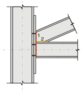
Join and source values are shown on the schematic drawing. |
|
Preview
Includes a preview of the merge. The selection made and the entered values can be followed simultaneously in the preview. |
Design Inputs Tab
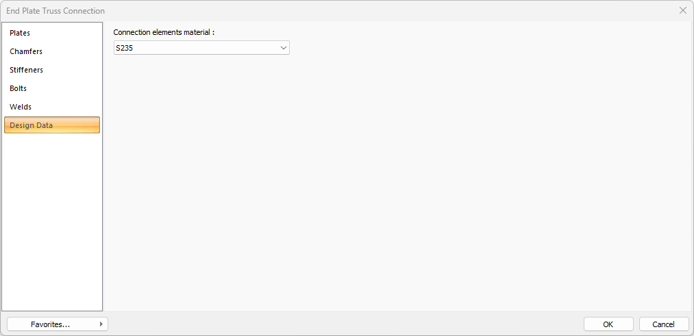
In the design data, the connection elements material is defined. The condition that the main element in the weld joint has less strength than the weld strength is controlled.

If necessary, click the list and define "Create New…". To create the connection elements material, give the information material definitions and values in the dialog that opens after clicking "Create New".
Next Topic