
Stair settings are included in the Stair Settings dialog, which includes parameters such as stair type, construction type, material, railing and handrail types . Before the stair is created, the stair settings dialog opens, and the settings made will be valid for the stairs to be drawn from now on.
Location of the Stair Settings Dialog
The stair that appears on the screen after running the Stair command is available in the helper toolbar.
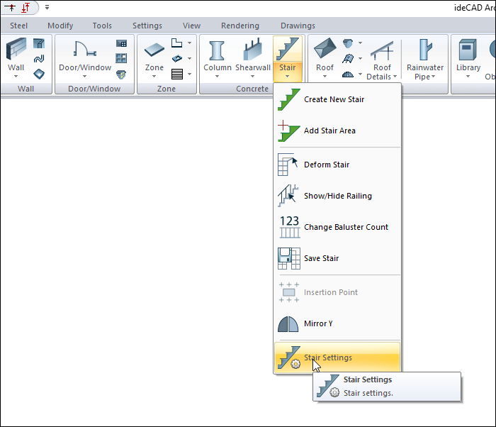
In Architectural Program
You can access it under the ribbon menu Home tab, Concrete title.
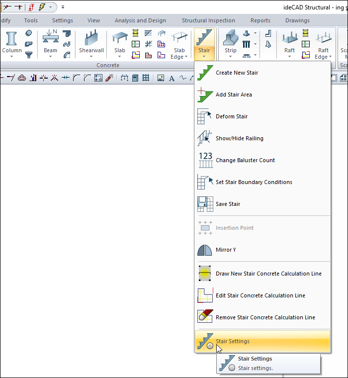
In Structural Program
You can reach it under the ribbon menu Concrete tab, Concrete title
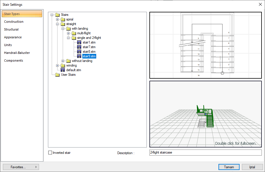
Stair Types Tab
|
Specifications |
|---|
|
Type list 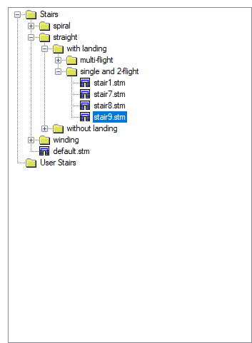
The stairs are organized under folders according to their types. The staircase to be drawn is selected under these folders. |
|
Plan 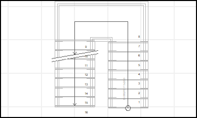
The plan view of the selected stair is included. |
|
Perspective 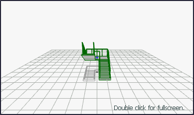
It has a three-dimensional view. It is possible to zoom in, zoom out, rotate the 3D image. In this way, the properties of the stairs can be examined in three dimensions. |
|
Inverted stair By marking it changes the exit direction of the stair flight. |
|
Description The description written for the stair is displayed on the Description line. User cannot intervene on this line. |
Construction Tab
|
Specifications |
|---|
|
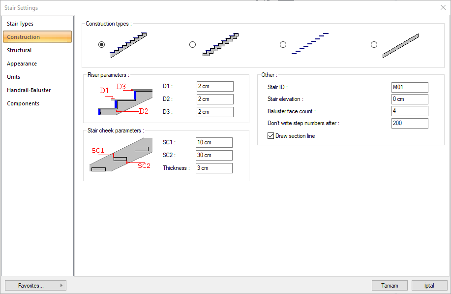
Construction types 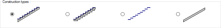
One of the straight, folded, bridge board and ramp type stair systems is selected by clicking with the left mouse button. |
|
Riser parameters 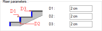
D1 is the step cladding nose length, D2 is the riser cladding thickness, D3 is the step cladding thickness. If cladding is not wanted, these values are entered as zero. |
|
Stair cheek parameters 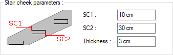
LK1 and LK2 determine the bridge board height. It is shown on the figure. The thickness parameter is the bridge board thickness. |
|
Stair ID The name of the stair is entered. |
|
Stair elevation The lower point of the stairs is the elevation measured from the floor base. |
|
Baluster face count The number of baluster surfaces determines the count of railing vertical surfaces (railing section). If the count of baluster surfaces is 4, the parapet cross section becomes square. |
|
Don’t write step numbers after The digits after the digit number entered here are not numbered on the stair. |
|
Draw section line If it is wanted to draw a section line on the stair, it is marked. |
Structural Tab
|
Specifications |
|---|
|
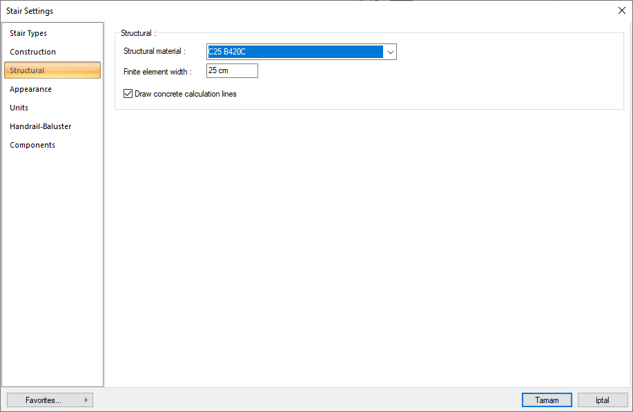
Structural material Select the structual material to be used in the stair element from the list. |
|
Finite element width
Enter the maximum finite element width to be taken as basis in shell calculation. The ideCAD analyzes shells by dividing them into trapezoidal form finite elements. Finite element width is automatically adjusted according to the shell shape, provided that it does not exceed the value entered in this row. |
|
Draw concrete calculation lines If it is wanted to show reinforced concrete calculation axes, it is marked. |
Appearance Tab
|
Specifications |
|---|
|
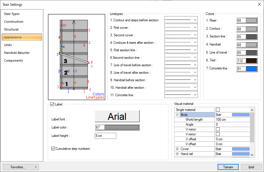
Schematic drawing 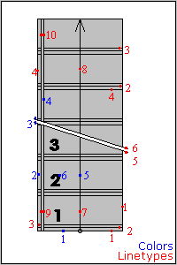
Which elements of the stair are defined by line types and colors are shown in schematic drawings and numbering. |
|
Linetypes 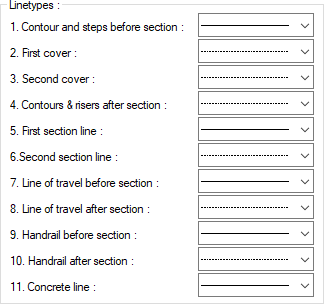
A separate line type is selected for the lines forming the stair in the plan. Clicking the down arrow buttons to the right of the boxes opens the list of line types. From this list, the wanted line type is selected by clicking with the left mouse button. The lines are numbered in red on the figure on the left. |
|
Colors 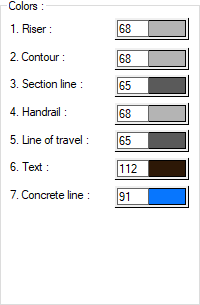
A separate color is chosen for the lines forming the stair in the plan. The lines are numbered in blue on the figure to the left of the dialog. When the color box is clicked, the appropriate color is selected from the window that opens. |
|
Label 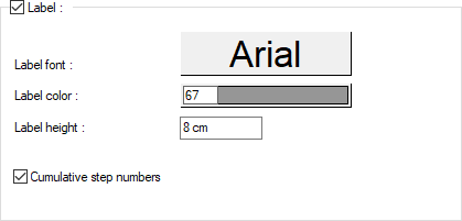
By marking the label, the number of risers, riser height and step width are shown on the stair. The font of the label font and the number of risers, the height and width of the digit is selected. The text color of the label color and the number of risers, the height and width of the digit is selected. The number of risers, the height of the digit and the height of the text of the width text are entered on the label height. The total number of digits is unmarked, and the number of risers, riser height and step width are shown separately on each branch. If checked, total values are shown. |
|
Visual material 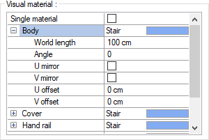
The material to be used on the body, cover, handrail and railing surfaces of the stairs is selected from the list. Surfaces are covered with the selected material and displayed as such in renderings. Texture length is entered into the world length. For example; If 1 is entered, the selected material texture is taken as 1 meter and covered on the relevant walls. The angle is the angle of the texture. In the U and V offset, the motion value in the x and y plane of the texture is entered. With U and V mirroring, the texture is symmetrical with respect to the y and x planes. By selecting the single material option, the material selected in the "Body" is used on all surfaces of the wall. |
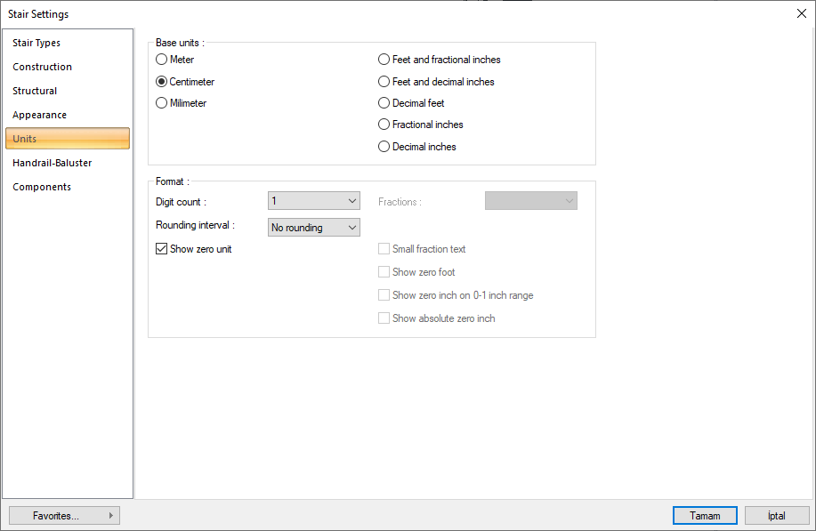
Units Tab
|
Specifications |
|---|
|
Basic units 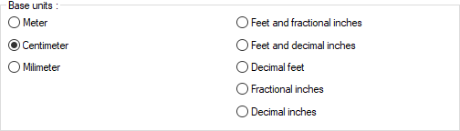
One of the selections is activated by clicking the left mouse button on the job. Meter : If checked, the unit of information text will be meters.
|
|
Digit count 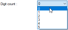
It determines how many digits will be shown after the comma. The desired number is selected from the list. For example, if 2 is selected, units will be shown as two digits after the comma. If 0 is selected, units will not be shown after the comma. |
|
Fractions 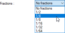
It determines the precision of the dimension to be made in fractional inch format. In the list, there are options with a sensitivity of 1/2, ¼, 1/8, 1/16, 1/32, 1/34. If "no fraction" is selected, units will appear without fractions. |
|
Rounding interval 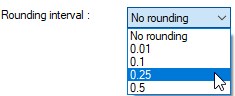
It determines the rounding range of the measurement to be made in meters, centimeters or millimeters. If No rounding is selected, the dimensioning is done at exact value. As the range gets larger, the dimensioning is rounded up to the selected range. |
|
Show zero unit If it is not checked, it does not show the zero and point on the left in dimensioning. For example, it measures 0.20 as 20. If marked, the value 0.20 is scaled as 0.20. |
|
Small fraction text When fractional inch format is selected, determines the fractional part to display in upper / lower case. If it is checked, the fraction is slightly above the integer and small, if not, the fraction is shown the same size next to the integer. |
|
Show zero foot Determines whether 0 is displayed in the 0-foot gauge (less than 1 foot gauge). For example, if it is not checked, it will show a measure of 0 '- 15 "as -15". If marked, it shows as 0'-15 ". |
|
Show zero inch on 0-1 inch range For example, a dimension inch with a value of 8'-0 1/6 "is in the range 0-1. If the option is not ticked, the value 8'-0 1/6" will be displayed as 8'-. In other words, inch values in the 0-1 range will not be displayed. |
|
Show absolute zero inch Determines whether to show zero inches in the dimension value where inches is absolute zero. For example, a dimension of exactly 10 'will be displayed as 10'-0 "if this option is selected. If not checked, it will be displayed as 10" -. |
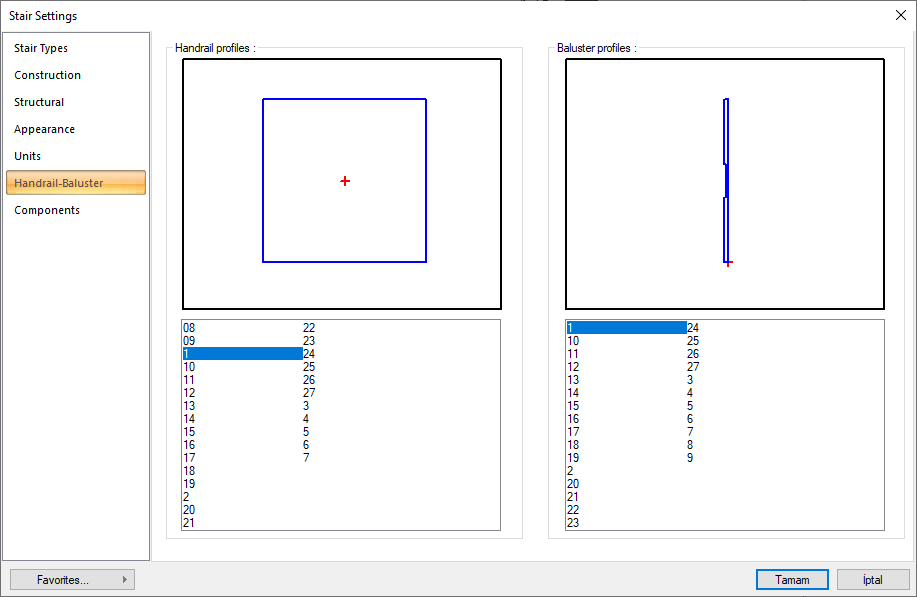
Handrail - Baluster Tab
|
Specifications |
|
|---|---|
|
Handrail profiles 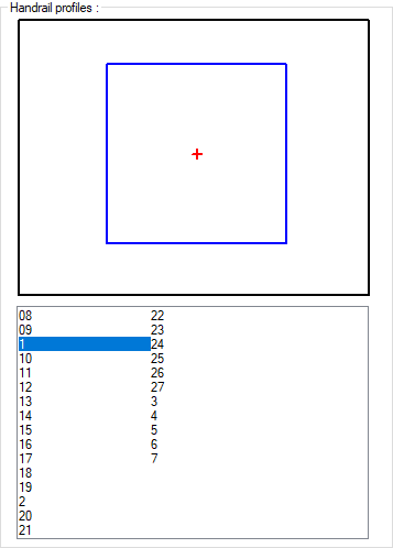
Select a handrail from the list of handrails by clicking with the left mouse button. The selected handrail section is displayed on the handrail screen. |
|
|
Baluster profiles 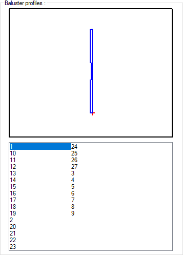
Select a baluster from the list of balusters by clicking the left mouse button. The selected baluster image is displayed on the baluster screen. |
|
Components Tab
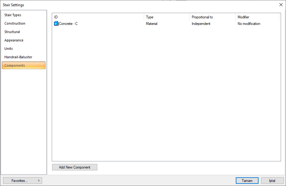
Add building components: Assigns the building materials defined for the detailed building components metering to the wall object.
-
Click the Add Building Component button.
-
The Component Selection dialog will open.
-
In this dialog, click the folder related to the material from the list on the left. Choose the material you want to use.
-
Set the parameters on the right.
-
Click the OK button. The "Component Selection" dialog will be closed. A summary line of the material will appear in the Building Components tab. More than one material assignment can be made to an object.
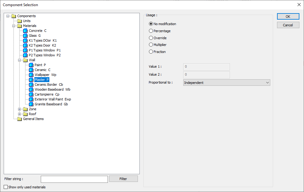
In the usage section
No modification: The amount of material to be assigned for the object in question is marked when it is desired to be used in the size that was previously specified in the material definition.
Percentage: This line is marked when it is desired to be used with the percentage of the amount previously determined in the material definition, as much as the value entered in the "Value 1" line in the same dialog. For example, if the material quantity is 70, if the line “Value 1” says 40, it means the material amount will be used up to 40 * 70%.
Override: This line is marked so that the quantity entered in the “Value 1” line in the same dialog will be used instead of the quantity previously determined in the material definition.
Multiplier: This line is marked in order to use the value found at the end of the multiplication of the value entered in the "Value 1" line in the same dialog with the amount previously determined in the material definition.
Fraction: This line is marked so that the amount determined in the material definition before will be used as the fraction value created by the values entered in the "Value 1" and "Value 2" lines in the same dialog. "Value 1" is the denominator "Value 2" is the denominator.
Proportional to: It is determined to what scale-area, circumference, length etc.-, region-side area, top, edge etc.- the material will be proportioned to. The content of the proportional list box is automatically determined according to the object and the size of the material. For example, a different list will be created if an operation is made for the column, a different list will be created for the library, a different list for the volume, and a different list for the field.
Following are the lines that appear in the proportion list according to the stair and material size.
|
Stairs |
||
|
Measure |
Listed |
Explanation |
|
Constant |
Independent |
The fixed measure used will be used exactly as the amount. |
|
Length |
Independent |
It means that the length measure found while defining the material will be used exactly as the length value. |
|
Line of travel length |
It means that the length of the material will be found by multiplying the length measurement found when defining the material and the length of the exit line of the ladder. |
|
|
Area |
Independent |
The area measure found when defining the material will be used exactly as the area of the material. |
|
Top area |
It means that the area measure found when defining the material will be multiplied by the area of the upper surface of the ladder. |
|
|
Volume |
Independent |
The volume measure found when defining the material will be used exactly as the volume of the material. |
|
Count |
Independent |
The number measure found while defining the material will be used exactly as the material number. |
|
|
Count |
The number measure found while defining the material will be used exactly as the material number. |
|
|
Riser count |
The number measure found when defining the material will be used by multiplying the number of rises of the stair. |
Next Topic