
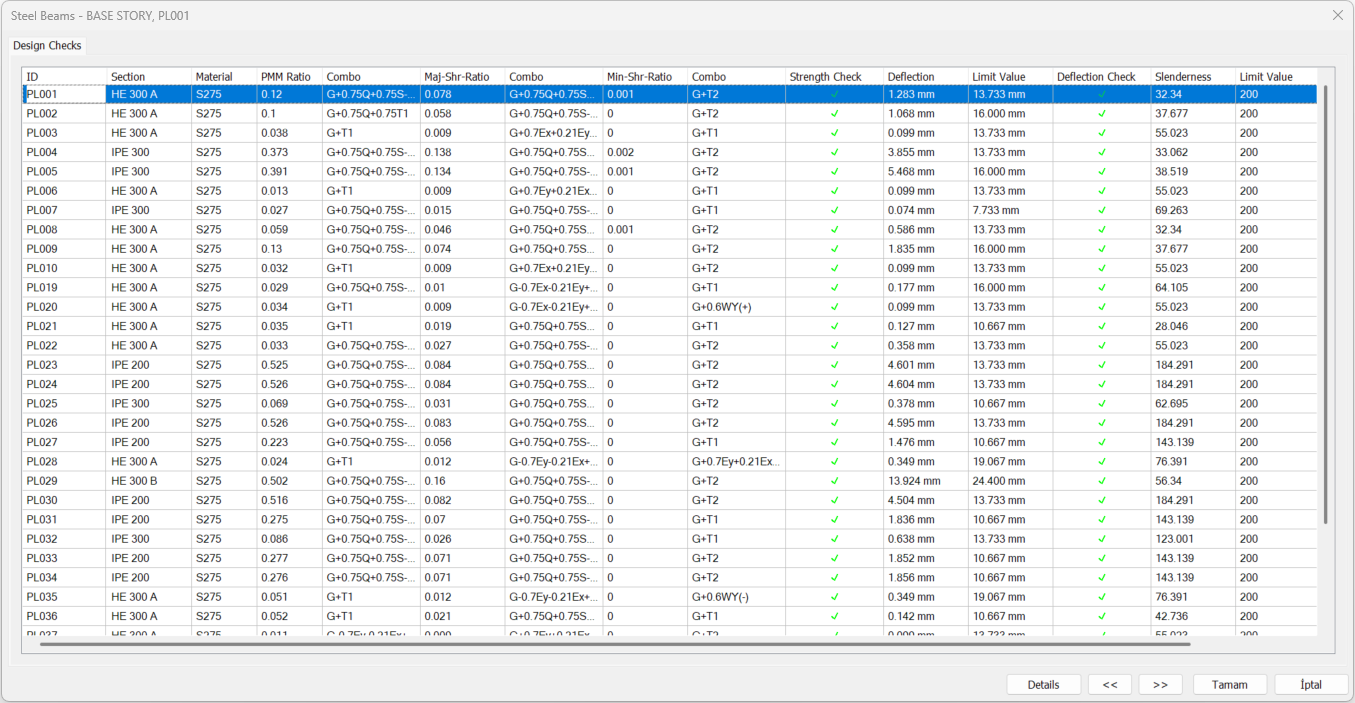
Steel beam design results and failure conditions for steel beams are displayed in the Steel Beams dialog. The Steel Beams dialog displays PMM ratios, combinations and deflection results. In the “ Details ” tab, material and section properties, internal force values, axial compressive strength, bending moment strength in strong and weak axis, design variables and lateral stiffness coefficients (K coefficient, L factor etc.) and PMM ratio are displayed.
Location of Steel Beams Dialogue
After the analysis is done, you can access it by clicking the Beam command under the Steel Design heading in the ribbon menu Analysis and Design tab .
Steel Beams
|
Specifications |
|---|
|
ID 
It is the name of the steel beam in the plan. |
|
Section 
It is the section used in steel beam. |
|
Material It is the material used in steel beam. |
|
PMM Ratio 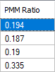
It is the ratio of requirement to section capacity (PMM Ratio = Need/Capacity). |
|
Combo 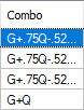
It is the load combination that produces the most unfavorable PMM ratio. |
|
Maj-Shr-Ratio 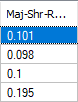
It is the ratio of the shear force in the major direction of the section to the capacity in the major direction. |
|
Combo 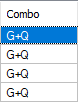
It is the load combination that produces the most unfavorable stress ratio in the major direction. |
|
Min-Shr-Ratio 
It is the ratio of the shear force in the minor direction of the section to the capacity in the minor direction. |
|
Combo 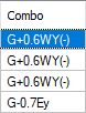
It is the load combination that produces the most negative stress ratio in the minor direction. |
|
Strength check 
It is an information box whose sign changes according to the presence or absence of negativity in the section. |
|
Deflection 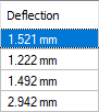
It is the deflection value made by the steel beam. |
|
Limit value 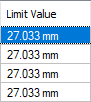
It is the value of the maximum allowed deflection of the element calculated according to the limit value determined from the design tab of the steel beam settings. |
|
Deflection check 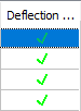
It is an information box whose sign changes depending on whether the deflection limit is exceeded or not. |
|
Slenderness 
It is the slenderness value of the steel beam. |
|
Limit Value 
It is the maximum slenderness value allowed in the steel beam. |
|
Details Design details are shown in detail. |
|
Previous The cursor moves to the previous line. |
|
Next The cursor goes to the next line. |
|
OK It saves the changes made and closes the dialog. |
|
Cancel Closes the dialog without saving the changes made. |
|
Summary Information The summary information about the line where the cursor is located is given in the name of the dialog in story, pose format. 
For example BASE STORY, SB001 |
|
Using the Shift key In this tab, you can select more than one row with the Shift key, enter a value by double-clicking any cell whose value is open to change, and make that value apply to all selected rows. |
|
Using the Ctrl key Ctrl key selects the lines in between one by one. |
Design Details
|
Specifications |
|---|
|
Schematic drawing 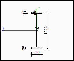
|
|
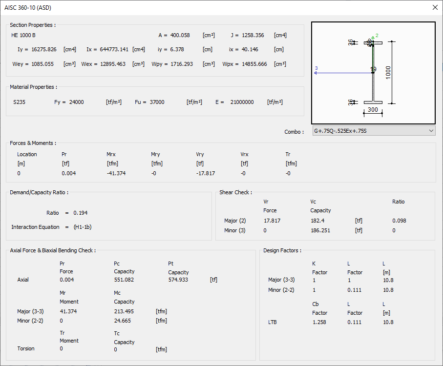
Section properties 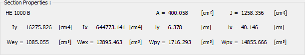
It is the part where the name and geometric properties of the section take place.
|
|
Material properties 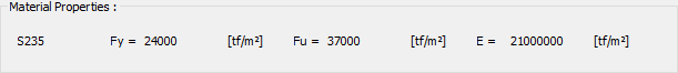
The properties of the steel material used in the section are listed.
|
|
Forces and moments 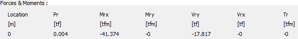
Internal forces occurring in the element, belonging to the selected load combination, are shown in this section.
|
|
Combo The load combination is selected. |
|
Demand/capacity ratio 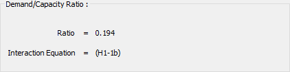
The demand/capacity ratio in the section of the selected load combination is displayed.
|
|
Shear check 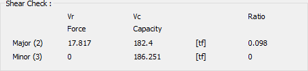
The shear capacity ratio of the steel beam is shown.
|
|
Axial force and biaxial bending control 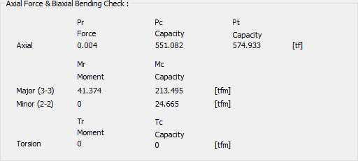
The axial capacity and moment capacity ratios of the steel beam are shown.
|
|
Design factors 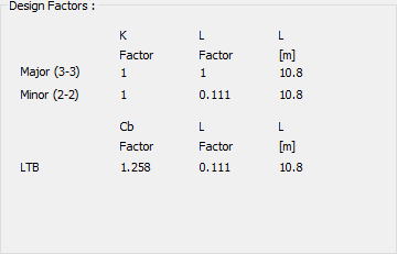
K factor: It is the effective length coefficient used in calculations.
|
Next Topic
Related Topics