
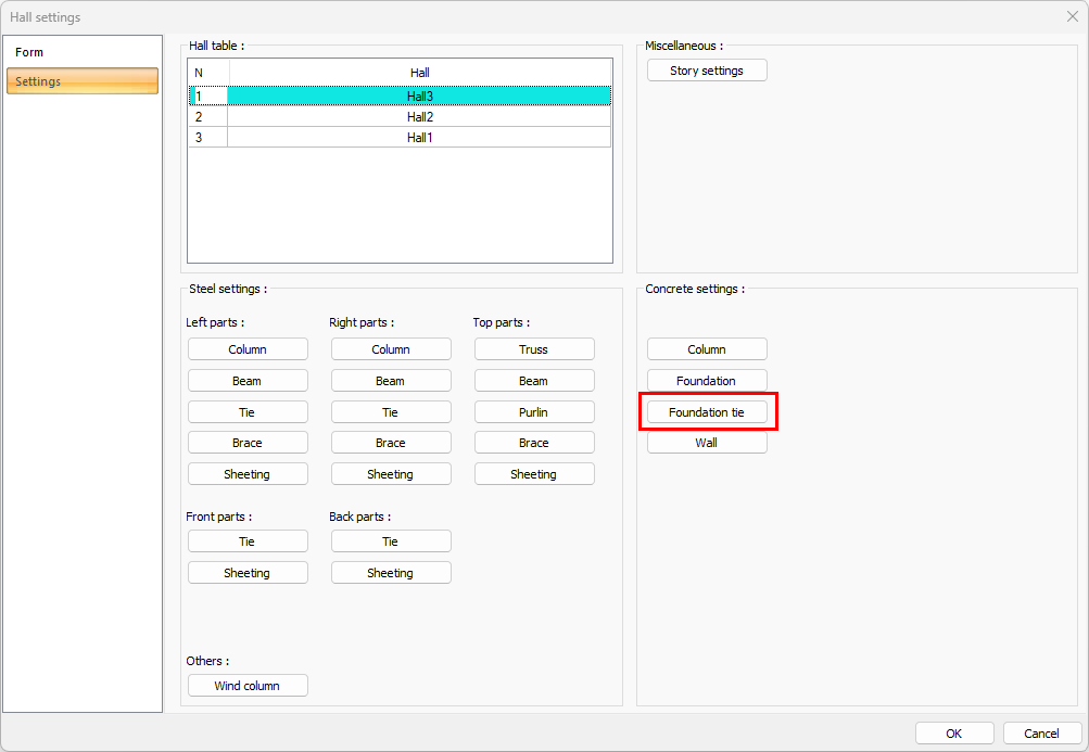
The hall foundation tie settings are changed by clicking the Foundation Tie button from the hall settings dialog settings tab.
Location of Foundation Tie Settings
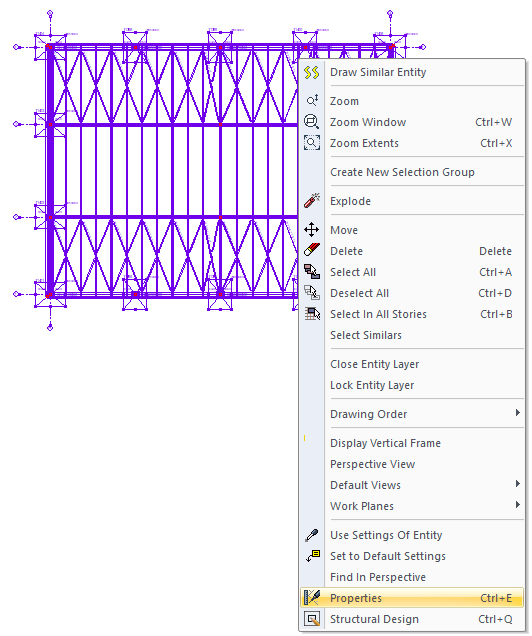
Select the hall where you want to change the foundation tie settings and click the right mouse button. Click the Properties line from the right click menu that opens. In hall setting dialog settings tab, click the foundation tie button.
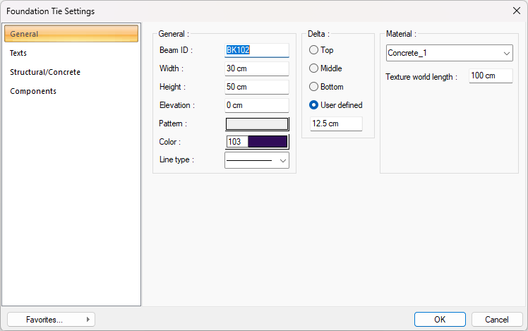
General Tab
|
Specifications |
|---|
|
Beam ID Foundation tie name is created by placing BK index in front of the number entered here (such as BK1, BK15). The program increments these names in the order in which the beams are drawn. The foundation tie names can also be changed after the foundation ties are drawn. The changed beam names do not have to be K. Any name can be used. |
|
Width The foundation tie width is entered. Beam width refers to the width of the beam in plan. The beam width is smaller than the beam height in drooping beams and larger in inclined beams. |
|
Height The beam height is entered. The beam height determines the height of the beam starting from the floor ceiling, downwards. While entering the beam height, the floor height and lower wall heights should be taken into account. Because these heights are under user control. The program does not make any automatic adjustments. |
|
Elevation The vertical distance (elevation) of the upper face of the beam measured from the floor base. It can be either (+) or (-) value. Enter (+) for inverse beam and (-) for lower beam. |
|
Pattern It is the hatch type that applies to the beam. Clicking on pattern opens the Hatch Settings dialog. In this dialog, the desired scan type is selected from the hatch types table by clicking the left mouse button on the hatch type. Hatching color and ground color boxes are scrolled on the color palette that is opened by clicking with the left mouse button and holding down the button. The button is released when the desired color is reached. The color box turns into the selected color. If clicked together with the Shift key, the pen thickness of the relevant color can be adjusted. Clicking the OK button closes the dialog and returns to the beam settings dialog. The hatch type selected in the active hatch box is displayed with the selected colors. |
|
Color The beam is the color of the border lines. The color palette is scrolled by clicking and holding down the left mouse button. The button is released when the desired color is reached. The color box turns into the selected color. If clicked together with the Shift key, the pen thickness of the relevant color can be adjusted. Pen thickness is not noticeable on the screen. The drawing is valid when drawn on paper. |
|
Line type The line type of the line forming the tie beam is selected in the plan. Clicking the down arrow buttons to the right of the boxes opens the list of line types. From this list, the desired line type is selected by clicking with the left mouse button. |
|
Delta 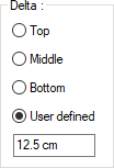
These are the options that determine where the beam will be defined. If the virtual beam axis that connects the joints at the two ends of the beam will coincide with the upper edge of the beam, the upper edge is selected, if it coincides with the lower edge, the lower option is selected, and if it passes through the middle of the beam, the middle option is selected. If the virtual beam axis will pass through another line, the Defined option is selected and the distance (meter) according to the upper edge of the beam is entered in the lower data entry box. The distance given should not be more than the beam thickness. |
|
Material The material to be covered on the beams in the solid model is selected. The beam is covered with the selected material and displayed in the solid model like this. Click on the down arrow button with the left mouse button. The appropriate material is selected from the opened material list. If there is no defined item, the list is blank. Adding material is done from the dialog that opens by clicking the Settings / Materials line. |
|
Texture word length Text length is entered. For example; If 1 is entered, the selected material texture width is taken as 1 meter and covered on the selected object. Considering that the texture is in the form of a square, the object surfaces are covered with 1x1 textures arranged side by side. |
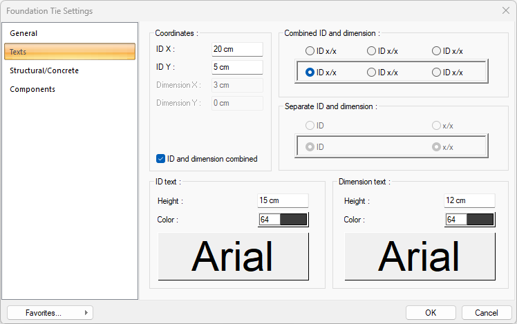
Texts Tab
|
Specifications |
|---|
|
ID X/ID Y X and Y coordinates are entered according to the beam upper left corner of the Beam Name text. Text If the X value is positive, the name text will move to the left, if it is negative, it will move to the right. Text scrolls up if the Y value is positive, and down if it is negative. |
|
Dimension X/Y X and Y coordinates are entered according to the upper right corner of the beam of the Beam Dimension text. If the dimension X value is positive, the dimension text shifts to the left, if it is negative, it shifts to the right. If the dimension Y value is positive, the dimension text will scroll up, and if it is negative, it will scroll down. |
|
ID and dimension combined If checked, the beam name and size are written together. If not checked, the beam name and beam size are written in the marked places in the dialog. |
|
Combined ID and dimension 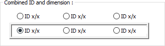
When the name and size together option is selected, determine the position where the name and size of the beam will be written according to the shape in the dialog. The program will place the name according to the location chosen when the beam was created. |
|
Separate ID and dimension 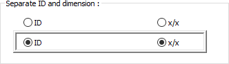
When the name and size together option is not checked, determine the position where the beam name and size will be written according to the shape in the dialog. The program will place the name according to the location chosen when the beam was created. |
|
ID text 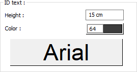
The height of the beam name text is entered. The color box is selected from the color palette that is opened by clicking the left mouse button. If the text button just below is clicked, the Font Settings dialog opens. From this dialog, Beam Name Text, font is set. |
|
Dimension text 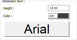
The height of the beam dimension text is entered. The color box is selected from the color palette that is opened by clicking the left mouse button. If the button below is clicked, the Font Settings dialog opens. From this dialog, Beam Dimension Text, font is set. |
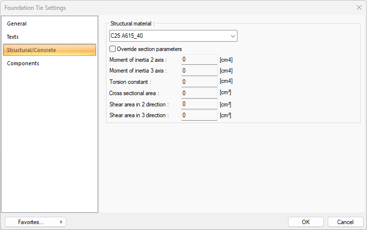
Structural/Concrete Tab
|
Specifications |
|---|
|
Structural material Select the static material to be used in the beam element from the list. Static material can be defined as a reinforced concrete element under Materials in Building Tree. |
|
Override section parameters 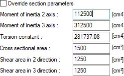
The section and geometric properties of the element are determined automatically and these are the values in accordance with the regulations. However, if you want to change the element section properties, mark this line and give the relevant values to the program. The program automatically calculates zero values and accepts non-zero entries as much as the entered value. 2 axis moment of inertia The element is the minor moment of inertia. I = b 3 h / 12
3 axis moment of inertia The element is the major moment of inertia. I = bh 3 /12 50/25 For example, in a column three axis rectangular moment of inertia 50.50.50.25 / 12 = 260416 cm 4 is calculated as. Torsional moment of inertia It is the moment of inertia that defines the torsional stiffness of the element. Cross-sectional area It is the cross-sectional area value of the element. For example, in a 50/25 rectangular column, the cross section area of the element is 50.25 = 1250 cm 2 . Cutting area in 2 direction The element is the cutting area in the minor direction. Cutting area = 5/6. b. d For example, in a 50/25 rectangular column, 5 / 6.50.25 = 1041 cm2 Cutting area in 2 direction The element is the cutting area in the major direction.
|
Components Tab
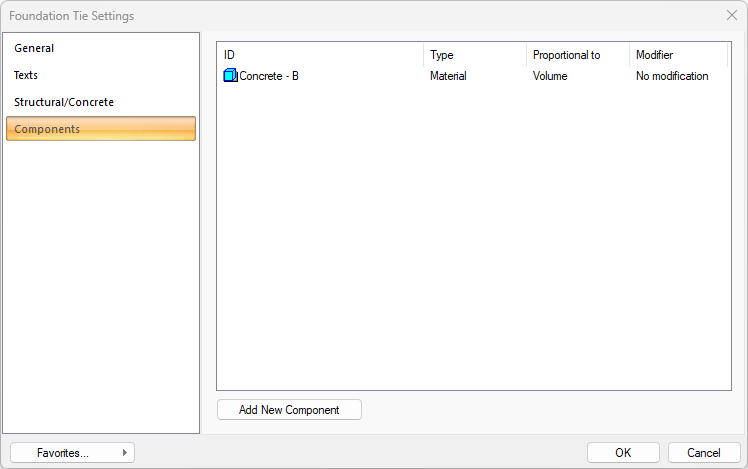
Add Building Components: Assigns the projected building materials to the object for detailed building components metrics.
-
Click on the building components button.
-
The Component Selection dialog will open.
-
In this dialog, click on the folder related to the material from the list on the left. Click on the material you want to use.
-
Set the parameters on the right.
-
Click the OK button. The "Component Selection" dialog will be closed. A summary line of the material will appear in the Building Components tab. More than one material assignment can be made to an object.
The parameters available in the component selection dialog are:
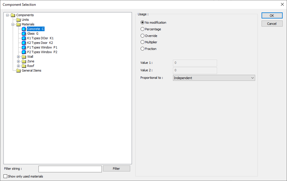
In the usage section
No modification: The amount of material to be assigned for the object in question is marked when it is desired to be used in the size that was previously specified in the material definition.
Percentage: This line is marked when it is desired to be used with the percentage of the amount previously determined in the material definition, as much as the value entered in the "Value 1" line in the same dialog. For example, if the material quantity is 70, if the line “Value 1” says 40, it means the material amount will be used up to 40 * 70%.
Override: This line is marked so that the quantity entered in the “Value 1” line in the same dialog will be used instead of the quantity previously determined in the material definition.
Multiplier: This line is marked in order to use the value found at the end of the multiplication of the value entered in the "Value 1" line in the same dialog with the amount previously determined in the material definition.
Fraction: This line is marked so that the amount determined in the material definition before will be used as the fraction value created by the values entered in the "Value 1" and "Value 2" lines in the same dialog. "Value 1" is the denominator "Value 2" is the denominator.
Proportional to: It is determined to what scale-area, circumference, length etc.-, region-side area, top, edge etc.- the material will be proportioned to. The content of the proportional list box is automatically determined according to the object and the size of the material. For example, a different list will be created if an operation is made for the column, a different list will be created for the library, a different list for the volume, and a different list for the field.
The lines that appear in the Proportion list according to the beam object and material size are as follows.
|
Foundation Tie |
||
|
Measure |
Listed |
Explanation |
|
Constant |
Independent |
The fixed measure used will be used exactly as the amount. |
|
Length |
Independent |
It means that the length measure found while defining the material will be used exactly as the length value. |
|
Front length |
It means that the length of the material will be found by multiplying the length of the length measured while defining the material and the length of the front side according to the beam viewing direction. |
|
|
Back length |
It means that the length of the material will be found by multiplying the length of the length measured while defining the material and the length of the back of the beam according to the viewing direction. |
|
|
Average length |
It means that the length of the material will be found by multiplying the length measurement found when defining the material and the average length value found from the length of the front and back sides of the beam. |
|
|
Average height |
It means the length of the material will be found by multiplying the length value found by taking the average of the height of the left and right ends of the beam with the length measure found while defining the material. |
|
|
Thickness |
It means that the length of the material will be found by multiplying the length measure found when defining the material and the thickness of the beam. |
|
|
Area |
Independent |
It means that the area measure found while defining the material will be used exactly as the amount. |
|
Front area |
The value to be found by multiplying the area of the area found when defining the material with the area of the surface on the front with respect to the beam's viewing direction means to be used as the material area. |
|
|
Back area |
It means that the value to be found by multiplying the area measure found while defining the material with the area of the surface on the back with respect to the beam's viewing direction will be used as the material area. |
|
|
Front and back area |
The value found by multiplying the area measure found when defining the material and the sum of the front and back areas of the beam will be used as the material area. |
|
|
Start area |
The value to be found by multiplying the area measure found when defining the material and the area of the surface on the left according to the beam's viewing direction, means to be used as the material area. |
|
|
End area |
The value to be found by multiplying the area measure found while defining the material and the area of the surface on the right according to the beam's viewing direction, means to be used as the material area. |
|
|
Start and end area |
When defining the material, the value found by multiplying the sum of the area measure found on the left and right sides of the beam with the surface area on the left and right means the material area will be used. |
|
|
Top area |
The value to be found by multiplying the area measure found when defining the material with the area of the surface remaining on the beam, means to be used as the material area. |
|
|
Bottom domain |
The value to be found by multiplying the area of the area found when defining the material and the area of the surface under the beam means to be used as the material area. |
|
|
Top and bottom area |
The value found by multiplying the total area of the area found when defining the material with the surface area on the upper and lower sides of the beam will be used as the material area. |
|
|
Side area |
The total value found by multiplying each of the surfaces on the sides of the beam with the area measure found when defining the material means to be used as the material area. |
|
|
Volume |
Independent |
The volume measurement found when defining the material will be used exactly as the volume value. |
|
Volume |
It means that the volume measurement found when defining the material will be used by multiplying the beam volume. |
|
|
Count |
Independent |
The count measure found while defining the material will be used exactly as the material count. |
|
Count |
The count measure found while defining the material will be used exactly as the material count. |
|
Next Topic