
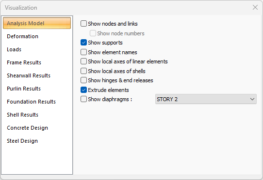
Details such as node point, element names, local axes to be displayed in the analysis model of the building are determined. Detail selection is made from the Analysis Model tab of the Visualization dialog.
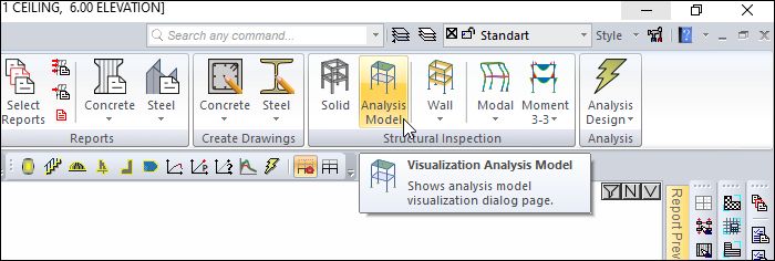
Location of Analysis Model View Feature
Ribbon menu Concrete tab Structural Inspection heading under the Analysis Model by clicking the command Analysis Model can be accessed from the tab.
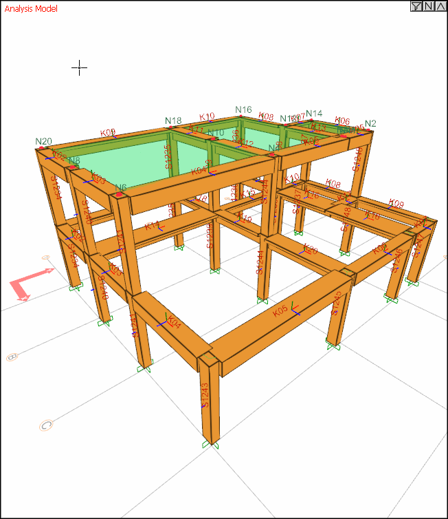
Sample screenshot with all options checked
Analysis Model Tab
|
Specifications |
|---|
|
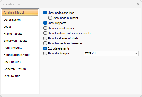
Show nodes and links If checked, all nodes created to element joins in the analysis model are shown as red points. 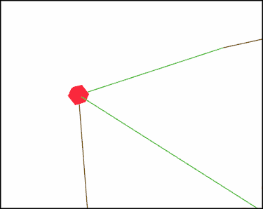
|
Show node numbers
Activates if show node numbers is checked. If checked, the names of all joints are also shown. 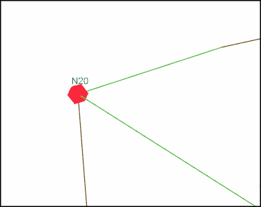
|
|
Show supports If checked, the supports in the frame system are shown. |
|
Show element names If checked, the names of the elements are shown above each element. For example K109, S1235 as the name of the element. 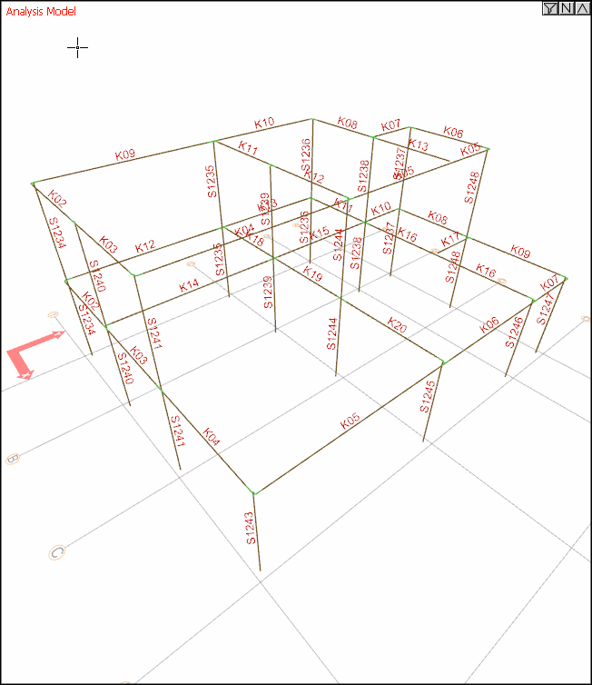
|
|
Show local axes of linear elements If checked, the local axes of the linear elements are shown on the elements. For more detailed information on Linear Element Local Axes. 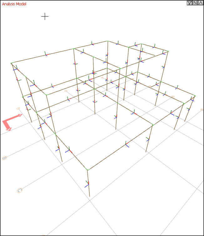
|
|
Show local axes of shells If checked, the local axes of the shell elements are shown on the elements. For more detailed information on Shell Elements Local Axes. |
|
Show hinges & end releases If checked, the information of the elements with hinges and end releases is displayed on the element. 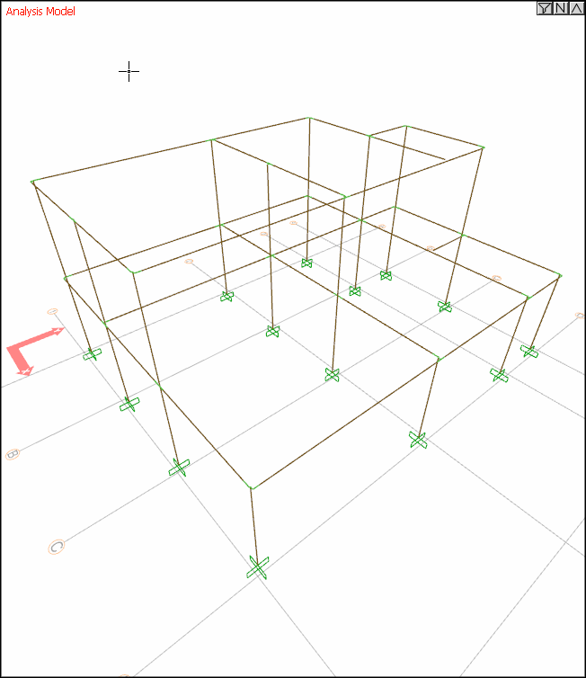
|
|
Extrude elements If checked, the frame system is shown as solid (solid). If not checked, it is shown as a line (bar). 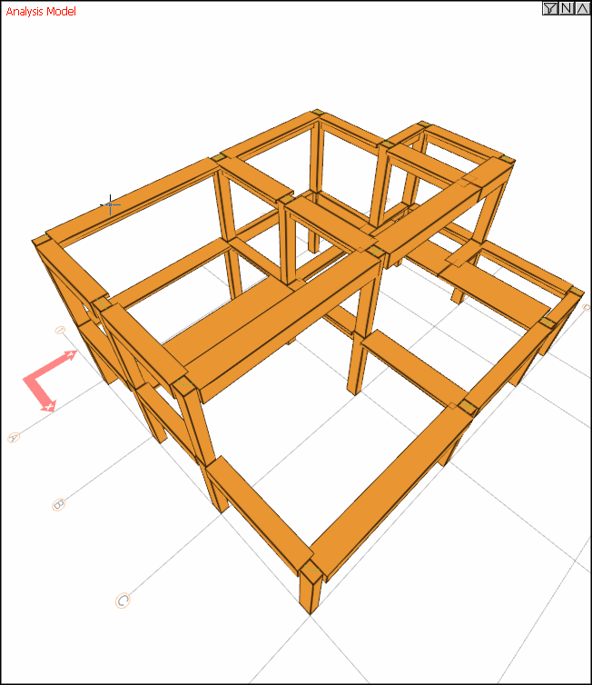
|
|
Show diaphragms If this option is checked, after analysis, all diaphragms in the system are shown according to the selected story. 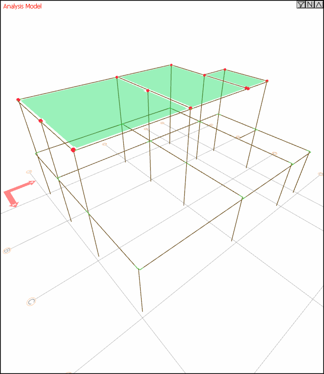
|
Next Topic