
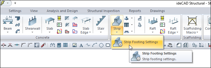
With the Strip Footing Settings command, settings such as strip footing dimensions, heights, elevation, drawing, material selection, structural material can be accessed.
Location of Strip Footing Settings Dialog
It is available in the Strip Footing auxiliary toolbar that appears after the Strip command is run.
Also, you can access it under the Concrete tab Foundation title in the ribbon menu .
General Settings Tab
|
Specifications |
|---|
|
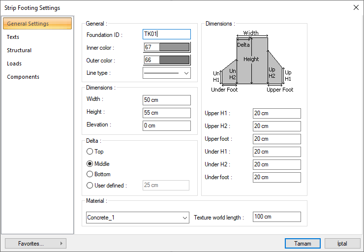
Foundation ID It is the name of the strip footing. The name of the strip footing is created by placing the TK index in front of the number entered here and the strip footing is written on the plan. The number is increased according to the order in which the strip footings are drawn (TK1, TK2, TK3 .... etc.). strip footing names can be changed later using the Label Entities command. The name index does not have to be TK. Different indices can be used for renaming. |
|
Inner color It is the color of the two inner lines that show the borders of the strip footing in the plan. The color palette is scrolled by clicking and holding down the left mouse button. The button is released when the desired color is reached. The color box turns into the selected color. If clicked together with the Shift key, the pen thickness of the relevant color can be adjusted. Pen thickness is not noticeable on the screen. The drawing is valid when drawn on paper. |
|
Outer color It is the color of the strip footing outline in the plan. These lines show the ampathons. If the Ampatman width is taken as zero, they will not be drawn. The color palette is scrolled by clicking and holding down the left mouse button. The button is released when the desired color is reached. The color box turns into the selected color. If clicked together with the Shift key, the pen thickness of the relevant color can be adjusted. Pen thickness is not noticeable on the screen. The drawing is valid when drawn on paper. |
|
Linetype The line type of the line forming the strip footing is selected in the plan. Clicking the down arrow buttons to the right of the boxes opens the list of line types. From this list, the desired line type is selected by clicking with the left mouse button. |
|
Width The width of the strip footing in the plan is entered. It is shown in the figure on the dialogue. |
|
Height The height of the strip footing (vertical height in the z direction). It is shown in the figure on the dialogue. |
|
Elevation The vertical (z direction) distance of the upper surface of the strip footing from the floor base. If the elevation value is zero, the upper surface of the strip footing coincides with the floor base. If a positive value is entered, the strip footing moves upwards, if a negative value is entered, it moves downwards. While the strip footing level is changed, the elevations of the columns resting on the relevant strip footing should also be taken into consideration and changed if necessary. |
|
Delta 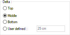
These are the options that determine where the strip footings will be defined. If the virtual strip footing axis joining the joints at the two ends of the strip footing will coincide with the upper edge of the strip footing according to the direction of view, the upper side is marked if it coincides with the lower edge, and the lower if it will pass through the middle of the strip footing. If the virtual strip footing axis will pass through another line, the Defined option is checked and the distance to the upper edge of the strip footing is entered in the lower data entry box. The distance given should not be more than the thickness of the strip footing. Strip footing edge lines are not outermost lines. The outermost lines are the ampatman lines. The two lines in the middle are foundation beam lines. The virtual base axis can be between or coincident with these two lines in the middle. It cannot go beyond these lines. |
|
Upper H1 The vertical (z-direction) height of the outer edge of the upper ampate from the basic viewing direction. It is shown in the cross sectional diagram on the dialog. |
|
Upper H2 The vertical (in z-direction) height (meters) of the inner edge of the upper ampate (the ampateman edge on the strip footing face side) from the basic viewing direction. It is shown in the cross sectional diagram on the dialog. |
|
Upper foot Plan width of the upper ampate from the basic viewing direction. This value is entered as zero to remove the upper ampate. It may be necessary to remove one of the ampatmans due to the building limit conditions. |
|
Under H1 The vertical (z-direction) height of the outer edge of the upper ampate from the basic viewing direction. It is shown in the cross sectional diagram on the dialog. |
|
Under H2 The vertical (z-direction) height of the inner edge of the upper ampate (ampateman edge on the fstrip footing face side) from the basic viewing direction. It is shown in the cross sectional diagram on the dialog. |
|
Under foot Plan width of the upper ampate from the basic viewing direction. This value is entered as zero to remove the lower ampate. It may be necessary to remove one of the ampatmans due to the building limit conditions. |
|
Material The material to be covered in the renderings of the strip footings is selected. The base is covered with the selected material and displayed as such in renderings. Click on the down arrow button with the left mouse button. The appropriate material is selected from the opened material list. |
|
Texture world length Texture word length is entered. For example; If 1 meter is entered, the selected material texture is taken as 1 meter and covered on the selected object. Considering that the texture is in the form of a square, the object surfaces are covered with 1x1 textures arranged side by side. |
Text Tab
|
Specifications |
|---|
|
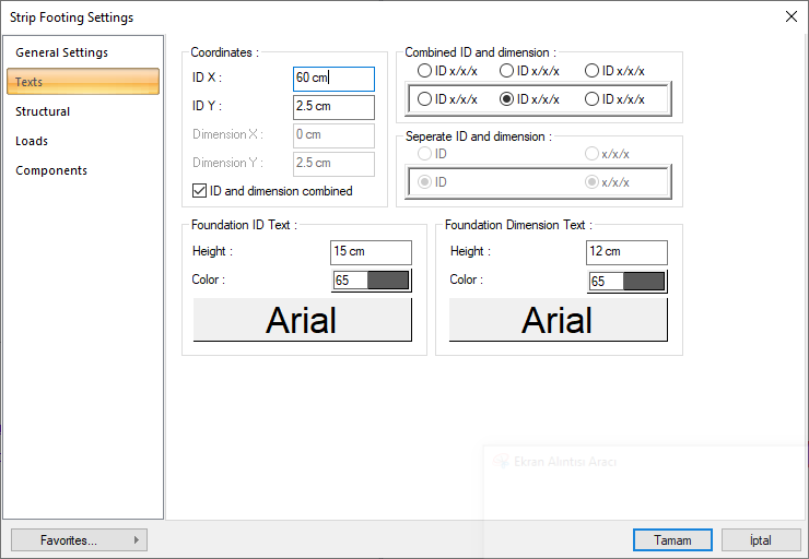
ID X/ID Y X and Y coordinates are entered according to the upper left corner of the strip footings ID text (if the article is on the strip footings) or lower corner (if the article is inside the strip footings). If the X value is positive, the text moves from the edge to the right, and if negative, it moves to the left. If the Y value is positive, the text will scroll up, and if it is negative, the text will scroll down. The directions specified here should be considered according to the viewing direction. If the name and size are printed together, the texts are placed according to these coordinates. |
|
Dimension X/Dimension Y X and Y coordinates are entered according to the upper right corner of the strip footings (if the article is above the strip footings) or the lower corner (if the article is inside the strip footings) of the strip footings dimension text. If the size X value is positive, the text moves from the edge to the left, if negative, the text moves to the right. If the Y value is positive, the text will scroll up, and if it is negative, the text will scroll down. The directions specified here should be considered according to the viewing direction. Not used if name and size are printed together. |
|
ID and dimension combined If checked, the strip footing name and size are written together. If not checked, the strip footing name and strip footing size are written in the marked places in the dialog. |
|
Combined ID and dimension 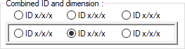
When the name and size together option is selected, determine the position where the name and size of the strip footing will be written according to the strip footing according to the figure in the dialog. The program will place the name according to the location chosen when the strip footing is established. |
|
Seperate ID and dimension 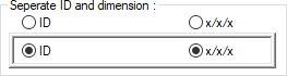
While the name and size together option is not checked, determine the position where the name and size of the strip footing will be written according to the shape in the dialog. The program will place the name according to the location chosen when the strip footing is established. |
|
Foundation ID text 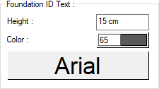
The height of the strip footing name text is entered. The color box is selected from the color palette that is opened by clicking the left mouse button. If the text button just below is clicked, the Font Settings dialog opens. From this dialog, Beam Name Text, font is set. |
|
Foundation dimension text 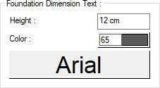
The height of the strip footing size text is entered. The color box is selected from the color palette that is opened by clicking the left mouse button. If the button below is clicked, the Font Settings dialog opens. From this dialog, Beam Dimension Text, font is set. |
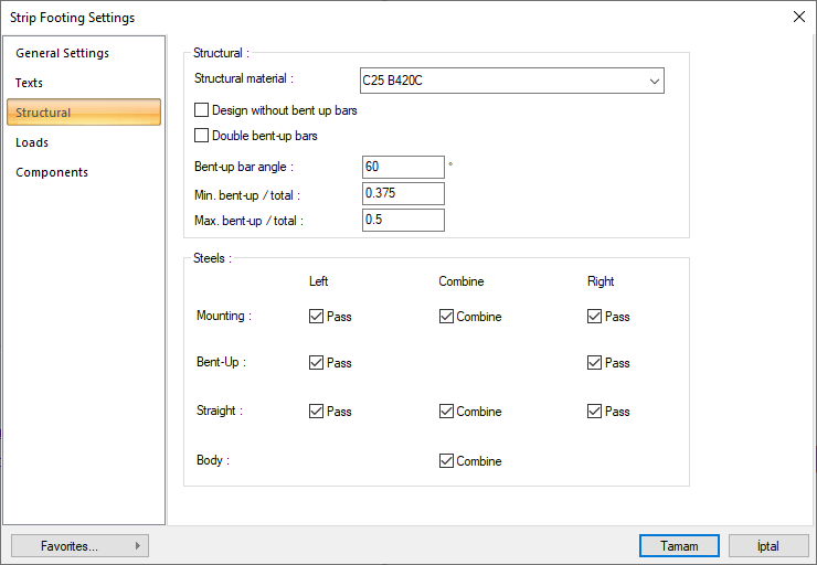
Structural Tab
|
Specifications |
|---|
|
Structural material Select the structual material to be used in the element from the list. Structural material can be defined as a reinforced concrete element under Materials in Building Tree. |
|
Design without bent up bars If the option is selected, pleat design is not made for continuous foundation beams. Strip footings are reinforced with upper and lower flat reinforcement. |
|
Double bent-up bars If you want to break into double piles in the strip footing, this option should be marked by clicking. |
|
Bent-up bar angle The number of degrees to break the pile of the strip footing is entered. The moment is brought to zero point due to the column to the pillar and it is broken by the value written here. |
|
Min bent-up/total It determines the minimum percentage of the total area of reinforcement in the span in the strip footing to be arranged in pleats. This value is used in conjunction with the defined straight and pleat diameters in the reinforcement selection and the "minimum distance between two reinforcements", "reinforcement margin" and "combination range allowed to select reinforcement", which can be defined in the project general settings. |
|
Max. bent-up/total In the strip footing, it determines what percentage of the total area of reinforcement in the span will be arranged in pleats. This value is used in conjunction with the defined straight and pleat diameters in the reinforcement selection and the "minimum distance between two reinforcements", "reinforcement margin" and "combination range allowed to select reinforcement", which can be defined in the project general settings. |
|
Steels 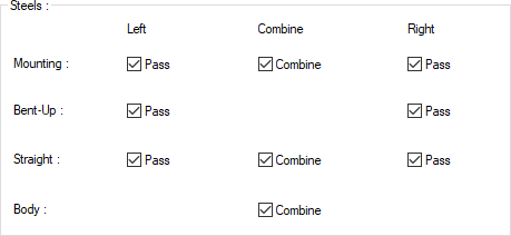
In this section, Mounting, Bent-up, Straight, Body rows and Left, Combine, Right columns are seen. |
|
Pass Check the pass boxes if you want the respective mounting, bent-up and straight bars to cross over to adjacent beams on continuous supports. |
|
Combine Check the combine box for mounting, bent-up and straight or body bars on both sides. In this case, if the diameter and quantity of the reinforcement are equal, the reinforcement will not be cut and combined. If it is not equal, you can combine the reinforcements if you intervene and equalize the diameters and numbers. |
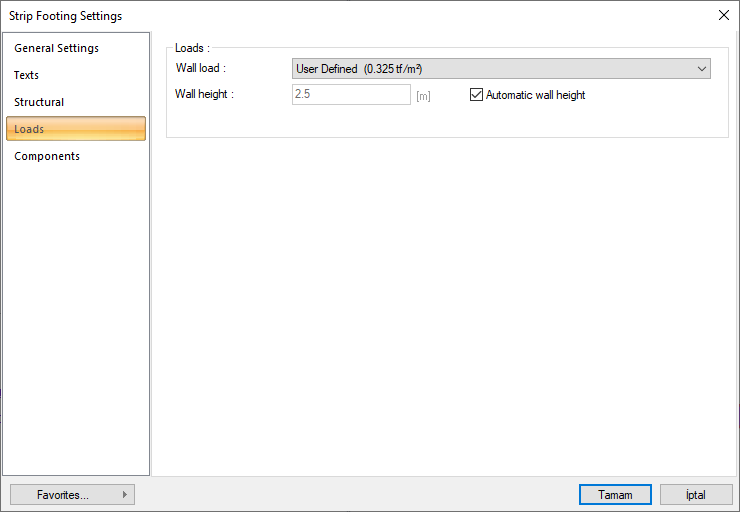
Loads Tab
|
Specifications |
|---|
|
Wall load You can select the appropriate wall load from the list. The wall loads in the list are those defined in the load library. If you want to specify a value other than these values as wall load, you can select the user-defined line from the list and enter the appropriate value from the dialog that opens. You can also add new wall loads to the load library yourself. |
|
Wall height Enter the height of the wall you want to be considered on the strip footing. |
|
Automatic wall height If this line is marked, the wall height to be considered on the strip footing is automatically calculated by the program. Wall height = Story height - Upper story beam height Note: If a wall is defined on a continuous foundation, a wall load must be defined in the wall settings. |
Components Tab
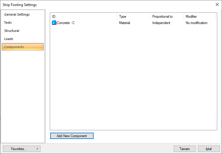
Add Building Components: Assigns the building materials defined for detailed building components metering to the object.
-
Click on the building components button.
-
The Component Selection dialog will open.
-
In this dialog, click on the folder related to the material from the list on the left. Click on the material you want to use.
-
Set the parameters on the right.
-
Click the OK button. The "Component Selection" dialog will be closed. A summary line of the material will appear in the Building Components tab. More than one material assignment can be made to an object.
The parameters available in the component selection dialog are:
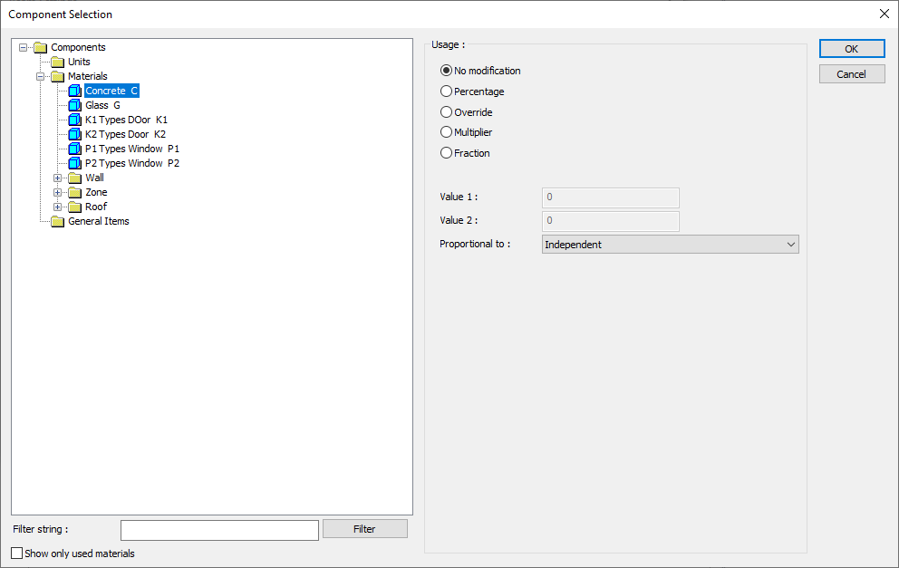
In the usage section
No modification: The amount of material to be assigned for the object in question is marked when it is desired to be used in the size that was previously specified in the material definition.
Percentage: This line is marked when it is desired to be used with the percentage of the amount previously determined in the material definition, as much as the value entered in the "Value 1" line in the same dialog. For example, if the material quantity is 70, if the line “Value 1” says 40, it means the material amount will be used up to 40 * 70%.
Override: This line is marked so that the quantity entered in the “Value 1” line in the same dialog will be used instead of the quantity previously determined in the material definition.
Multiplier: This line is marked in order to use the value found at the end of the multiplication of the value entered in the "Value 1" line in the same dialog with the amount previously determined in the material definition.
Fraction: This line is marked so that the amount determined in the material definition before will be used as the fraction value created by the values entered in the "Value 1" and "Value 2" lines in the same dialog. "Value 1" is the denominator "Value 2" is the denominator.
Proportional to: It is determined to what scale-area, circumference, length etc.-, region-side area, top, edge etc.- the material will be proportioned to. The content of the proportional list box is automatically determined according to the object and the size of the material. For example, a different list will be created if an operation is made for the column, a different list will be created for the library, a different list for the volume, and a different list for the field.
The lines that appear in the proportion list according to the basic object and material size are as follows:
|
Strip Footing |
||
|
Measure |
Listed |
Explanation |
|
Constant |
Independent |
The fixed measure used will be used exactly as the amount. |
|
Length |
Independent |
It means that the length measure found while defining the material will be used exactly as the length value. |
|
Average length |
It means that the length of the material will be found by multiplying the length measurement found while defining the material and the average length value found from the length of the front and back sides of the strip footing. |
|
|
Thickness |
It means that the length of the material will be found by multiplying the length measurement found when defining the material and the thickness of the strip footing. |
|
|
Height |
It means that the length of the material will be found by multiplying the length measurement found while defining the material and the height of the strip footing. |
|
|
Area |
Independent |
It means that the area measure found while defining the material will be used exactly as the amount. |
|
Volume |
Independent |
The volume measurement found when defining the material will be used exactly as the volume value. |
|
Volume |
It means that it will be used by multiplying the volume measurement found when defining the material and the volume of the strip footing. |
|
|
Count |
Independent |
The number measure found while defining the material will be used exactly as the material number. |
|
Count |
The count measure found while defining the material will be used exactly as the material count. |
|
Next Topic
Related Topics