
-
Concrete cover control is done automatically according to TS 500 Article 9.5.1 .
-
Minimum tensile reinforcement ratio, maximum reinforcement ratio, longitudinal reinforcement diameter control, web reinforcement spacing, web reinforcement diameter control are performed automatically according to TS 500 Article 7.3 .
-
Middle area stirrup gap control is done automatically according to TS 500, Article 8.1.6 .
-
Minimum reinforcement spacing control is done automatically according to TS 500 Article 9.5.2 .
-
Tensile and compression reinforcement ratio control is done automatically according to TS 500 Article 10.4.3 .
ICONS
A s = Tensile reinforcement cross section area
A ' s = Compressive reinforcement cross section area
b w = Beam body width
c c = Net concrete cover
d = Beam useful height
f ctd = Concrete design axial tensile strength
f yd = Longitudinal reinforcement design yield strength
V cr = Shear strength of thesection
V d = Design shear force
s = Stirrup spacing
ρ = Tensile reinforcement ratio
ρ b = Balanced reinforcement ratio
ρ ' = Pressure reinforcement ratio
ρ max = Maximum reinforcement ratio
ρ min = Minimum reinforcement ratio
According to TS500 Article 10.4.3 , the minimum longitudinal and transverse reinforcement ratios in all elements constituting the continuous foundations are defined by the proportions prescribed by this standard for beams and slabs. Compressive reinforcement of at least 1/3 of the tensile reinforcement shall be available in the compression zone of all sections under bending effect. For this reason , the beams section of TS 500 and other relevant sections have been taken into consideration while checking the reinforcement of the foundation beams .
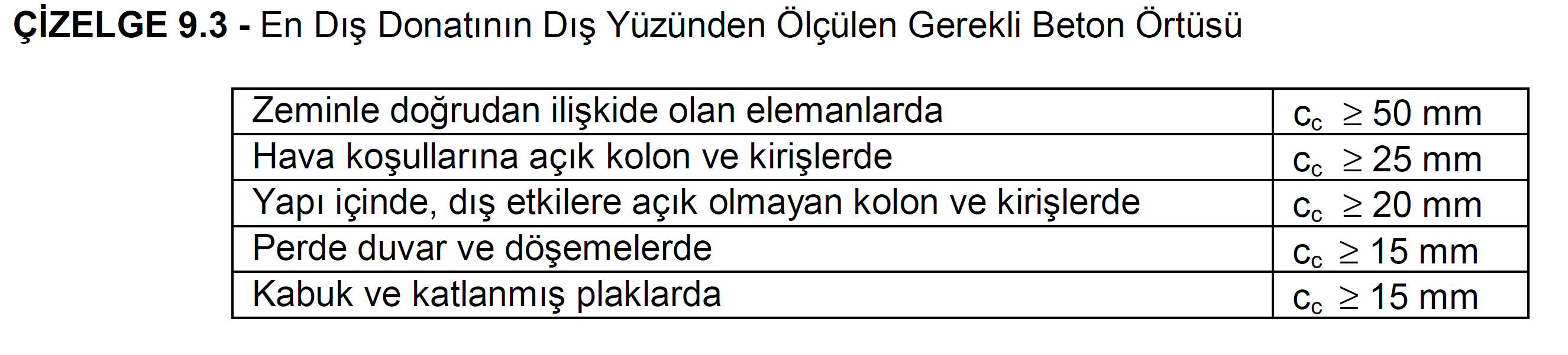
While applying the concrete cover control, 9.3 is taken into consideration in the Schedule given in TS 500, Article 9.5.1 . Therefore, in continuous foundations, the net concrete cover should be c c ≥ 50 mm.
Equation 7.3 given in 7.3 of TS 500 is used when applying minimum tensile reinforcement ratio control in continuous foundations . In these relations, ρ is tensile reinforcement ratio, A s tensile reinforcement cross-sectional area, b w beam body width and d beam useful height.

TS 500 - Balanced Reinforcement Ratio Condition


In these relations, ρ is the tensile reinforcement ratio.
In continuous foundations , the largest longitudinal reinforcement diameter is applied as 12 mm in accordance with Article 7.3 of TS 500 .
In continuous foundations , the largest body reinforcement interval is applied as 300 mm in accordance with TS 500 Article 7.3 .
In continuous foundations , the largest body reinforcement diameter is applied as 10 mm in accordance with Article 7.3 of TS 500 .
In continuous foundations, according to TS 500 Article 8.1.6 , the middle zone stirrup spacing cannot be more than half of the useful height (s≤d / 2). Also, for cases where V d > 3V cr , the stirrup interval should be s≤d / 4 applies.
In continuous foundations , according to TS 500 Article 9.5.2 , the minimum reinforcement interval is applied in such a way that the net spacing between the reinforcement bars in the same row is less than 4/3 of the maximum aggregate diameter and 25 mm.
In continuous foundations , it is applied in the compression zone in accordance with TS 500 Article 10.4.3 in a way that at least 1/3 of the tensile reinforcement is available.
Next Topic