
Concrete Drawings with ideCAD
|
Create Concrete Drawings with ideCAD like the Formwork plan, column application plan, column vertical expansions, beam expansions, etc. of the project whose Analysis and design is done. |
-
Click the Analysis+Design (F9) command.
-
“Do you want to perform analysis?” question will be asked.
-
Click the Yes button.
-
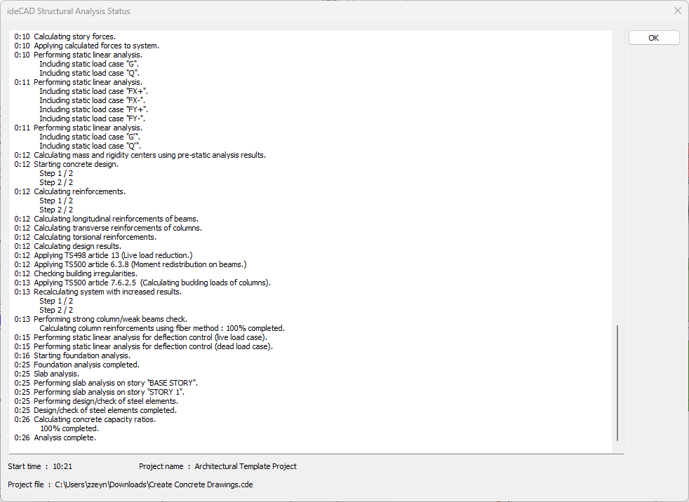
Wait for the analysis to complete in the Analysis Status window.
-
After completing the analysis, click the OK button to close the window.
-
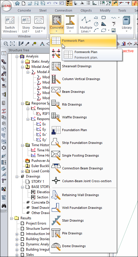
Click the Ribbon menu Drawings tab.
-
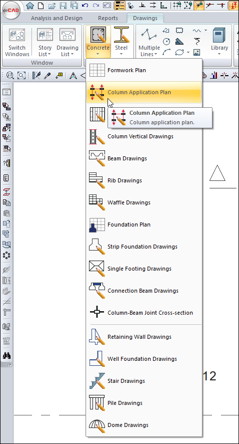
Open the Concrete drawing list from the Create drawing heading.
-
Click the Formwork Plan command.
-
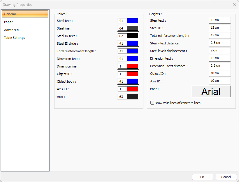
The Concrete Drawing Properties dialog will open.
-
Check the drawing properties and click the OK button.
-
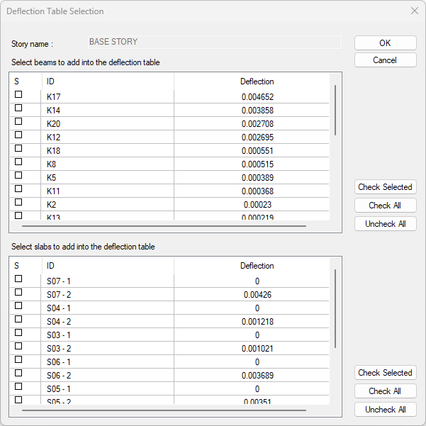
The deflection table selection dialog will open.
-
Click the OK button to close the dialog.
-
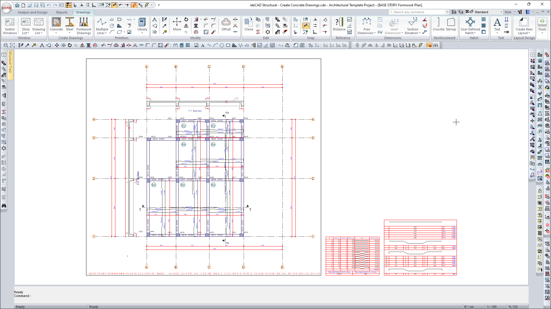
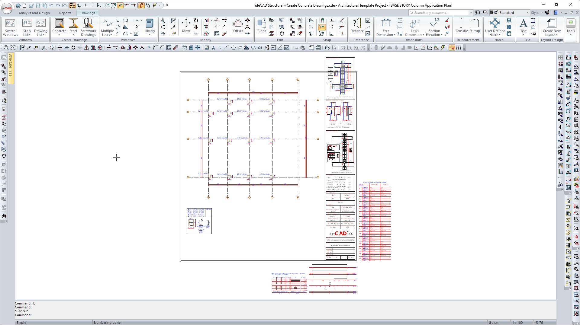
A Formwork Plan drawing will be created in the drawing edit window.
-
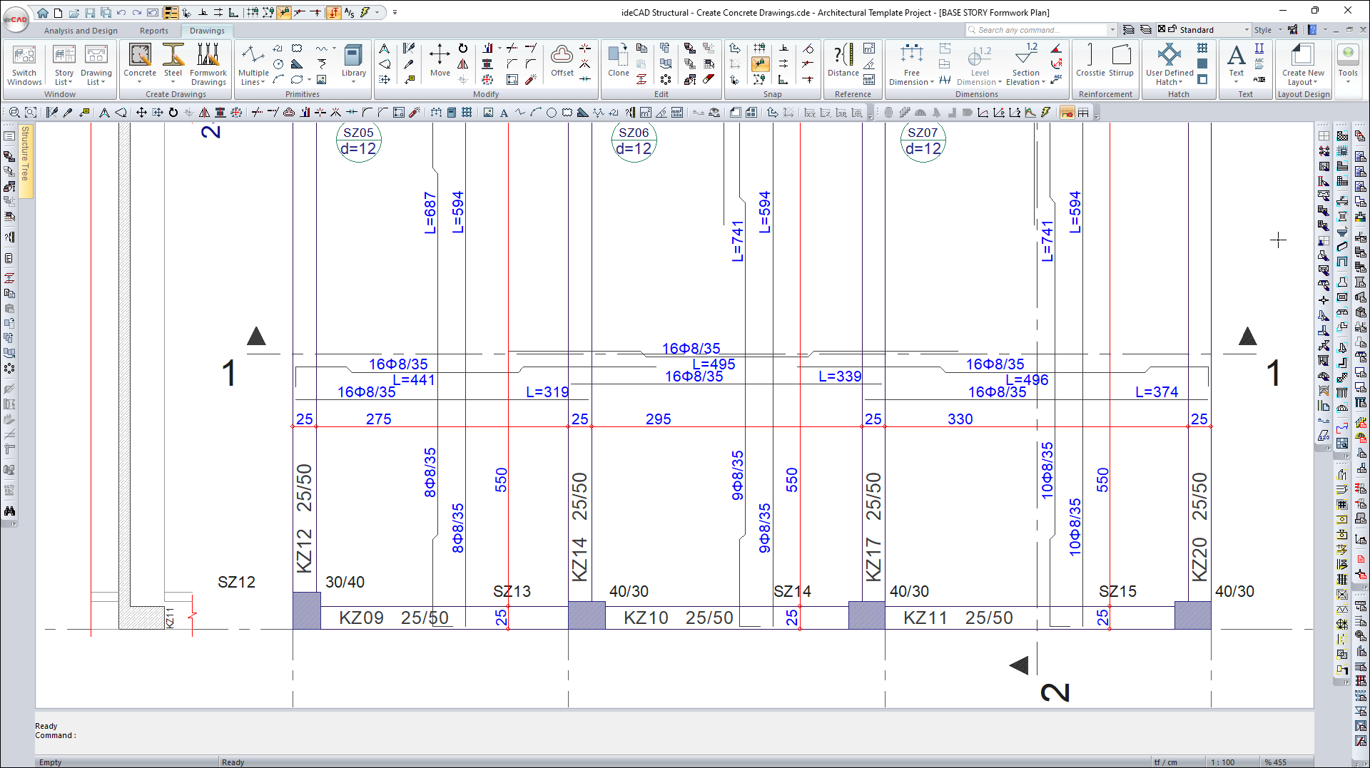
Concrete Drawings can be edited in the drawing editing window.
-
Click the Fast Move command.
-
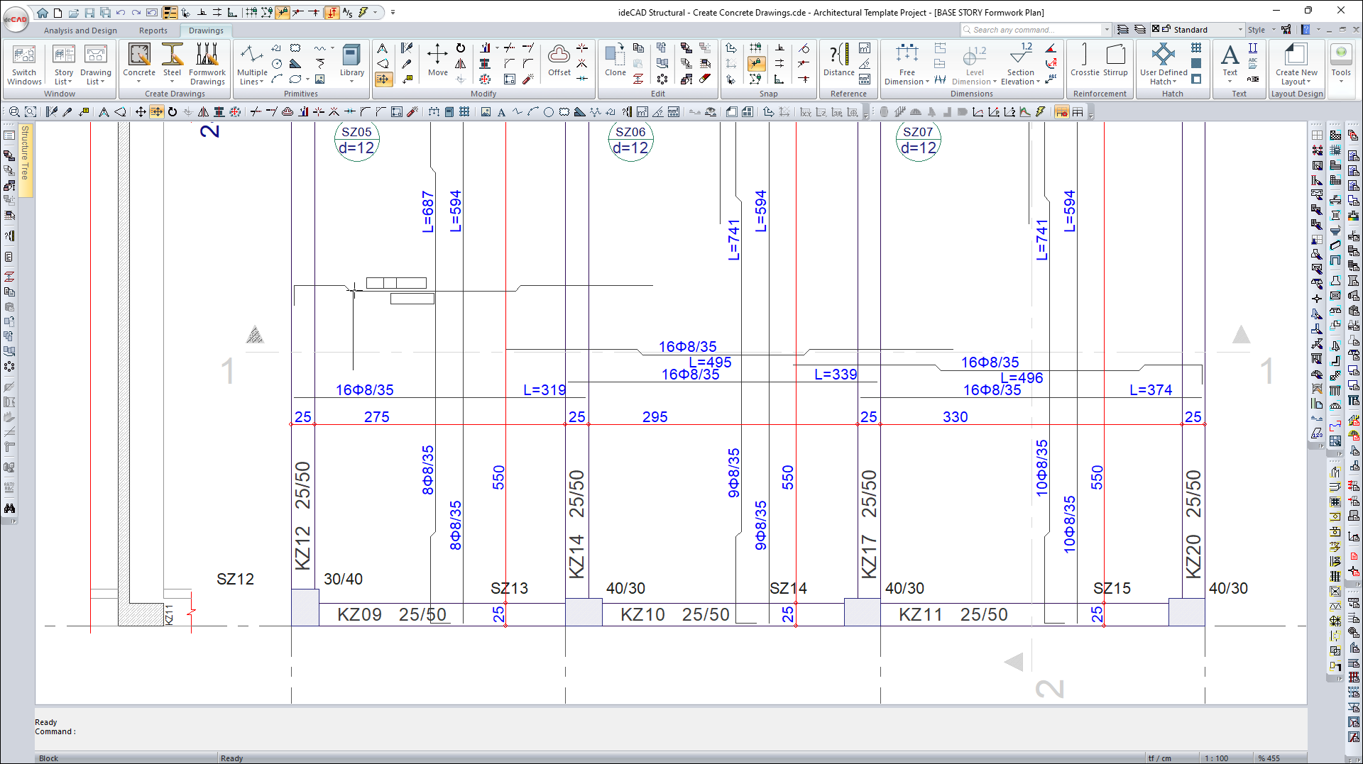
Click on the drawing block you want to move.
-
The drawing block will be selected.
-
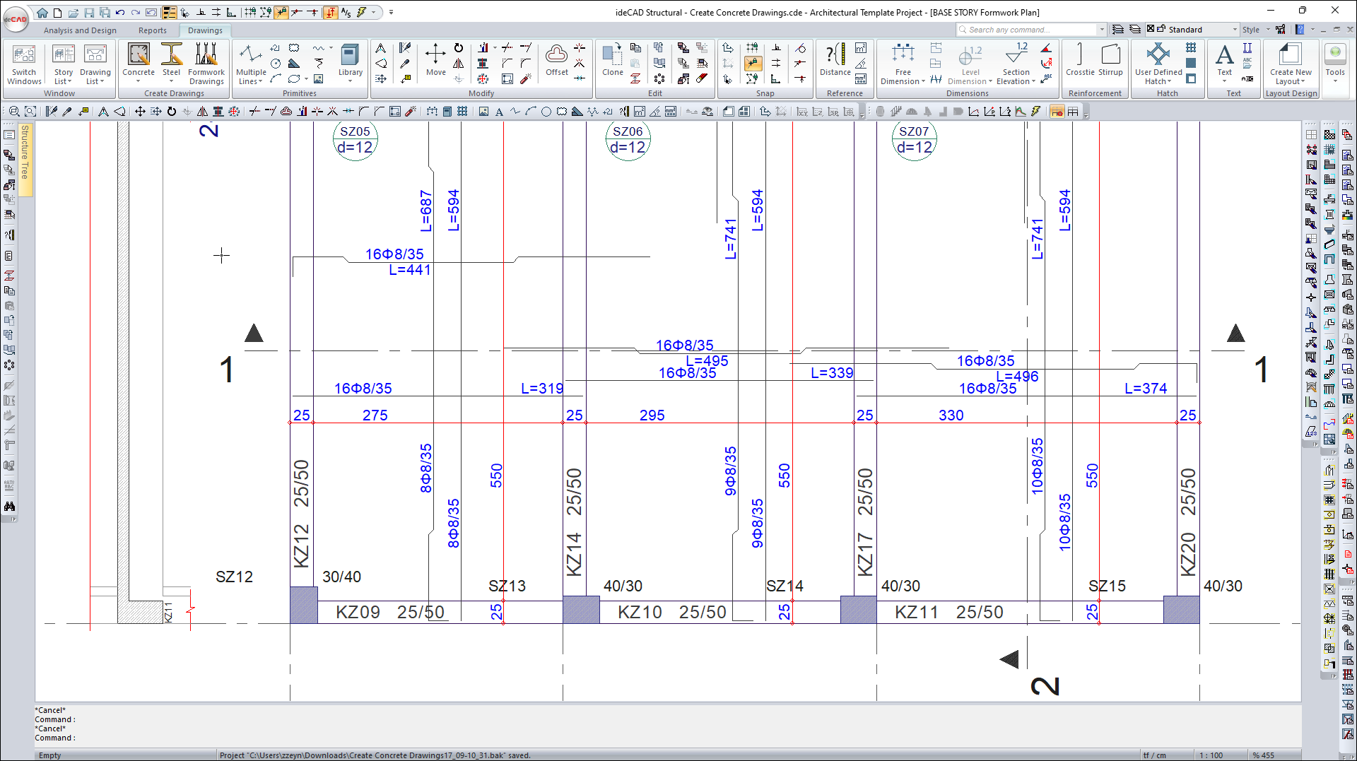
Move the block to the desired point and click with the left mouse button.
-
After completing the Fast Move operations, press the Esc key on the keyboard to exit the command.
-
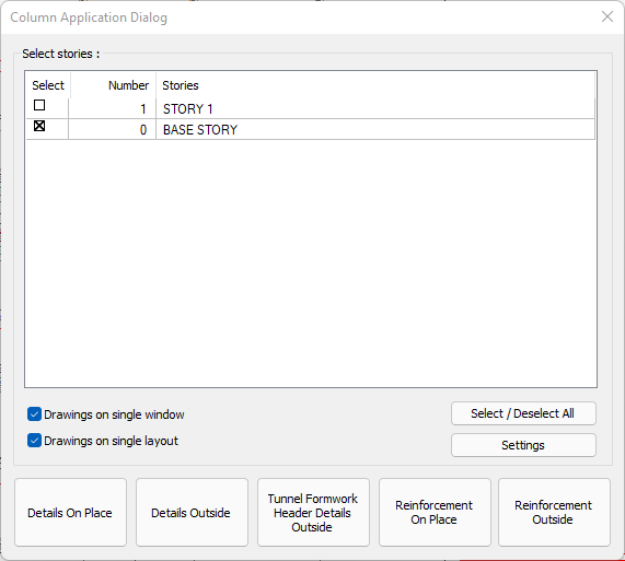
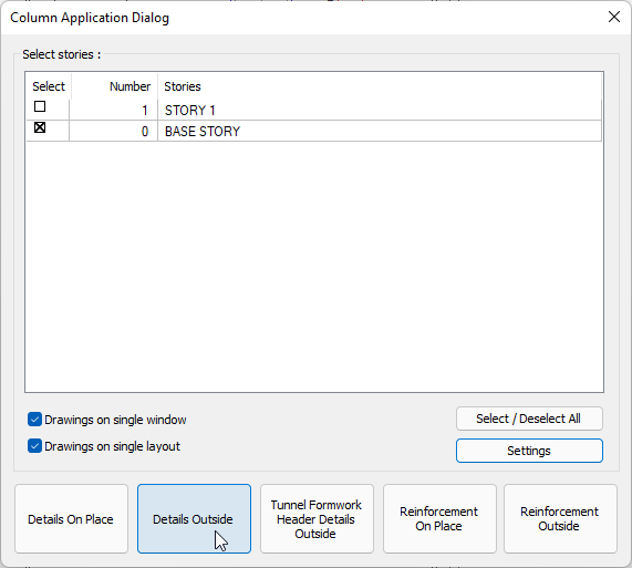
Click the Column Application Plan command from the Concrete list.
-
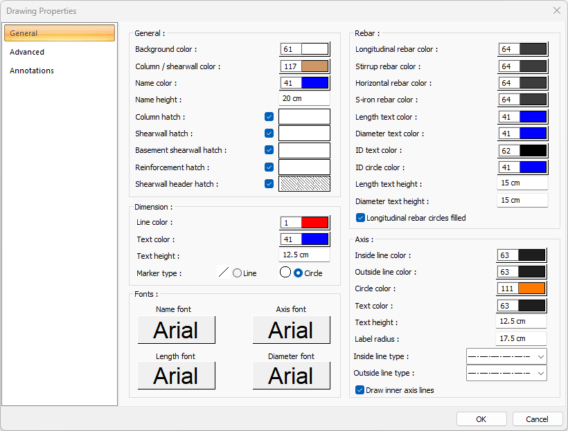
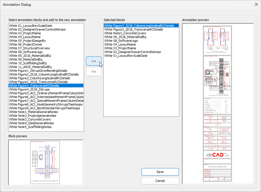
Click the Settings button from the Column Application Dialog that opens.
-
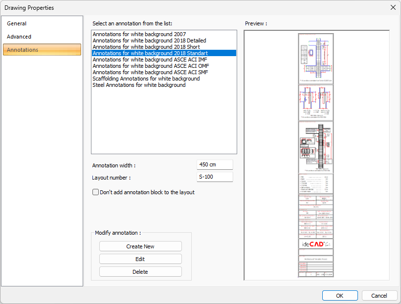
The Concrete Drawing Properties dialog will open.
-
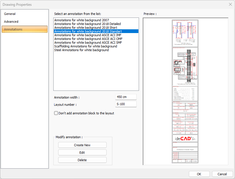
Click the Annotations tab.
-
The annotations to be created in the drawing are listed.
-
Select Annotation for white background 2018 Standart annotation.
-
Click the Edit button.
-
Select the Annotation block.
-
Click the right arrow to add it to the Selected Blocks list.
-
Selected blocks shown in the Block Preview will be added to the Annotation Preview.
-
Save the annotation by clicking the Save button.
-
Click the OK button to close the Drawing Properties dialog.
-
Click the Details Outside button.
-
Column Application Plan drawings will be created.
-
Click the Beam Drawings command from the Concrete list.
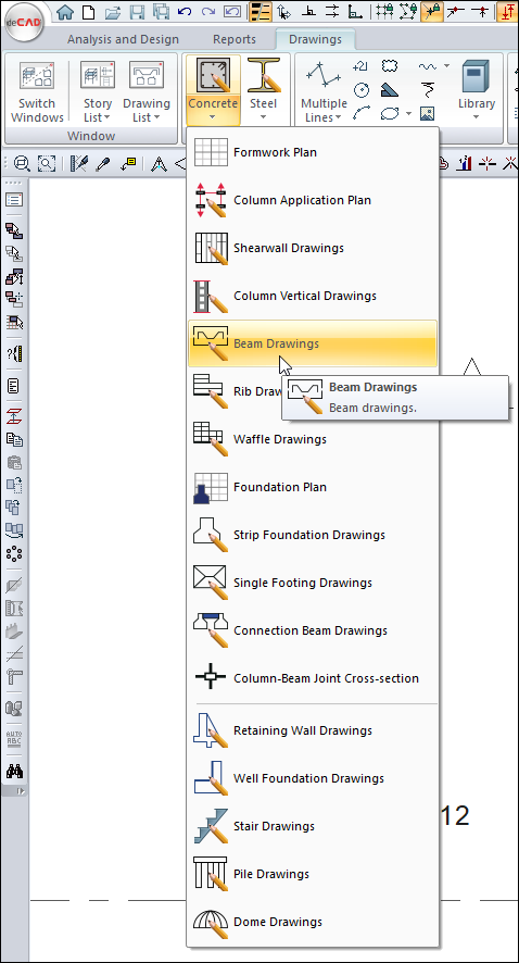
-
The Drawing Properties dialog will open.
-
Check the drawing properties and click the OK button.
-
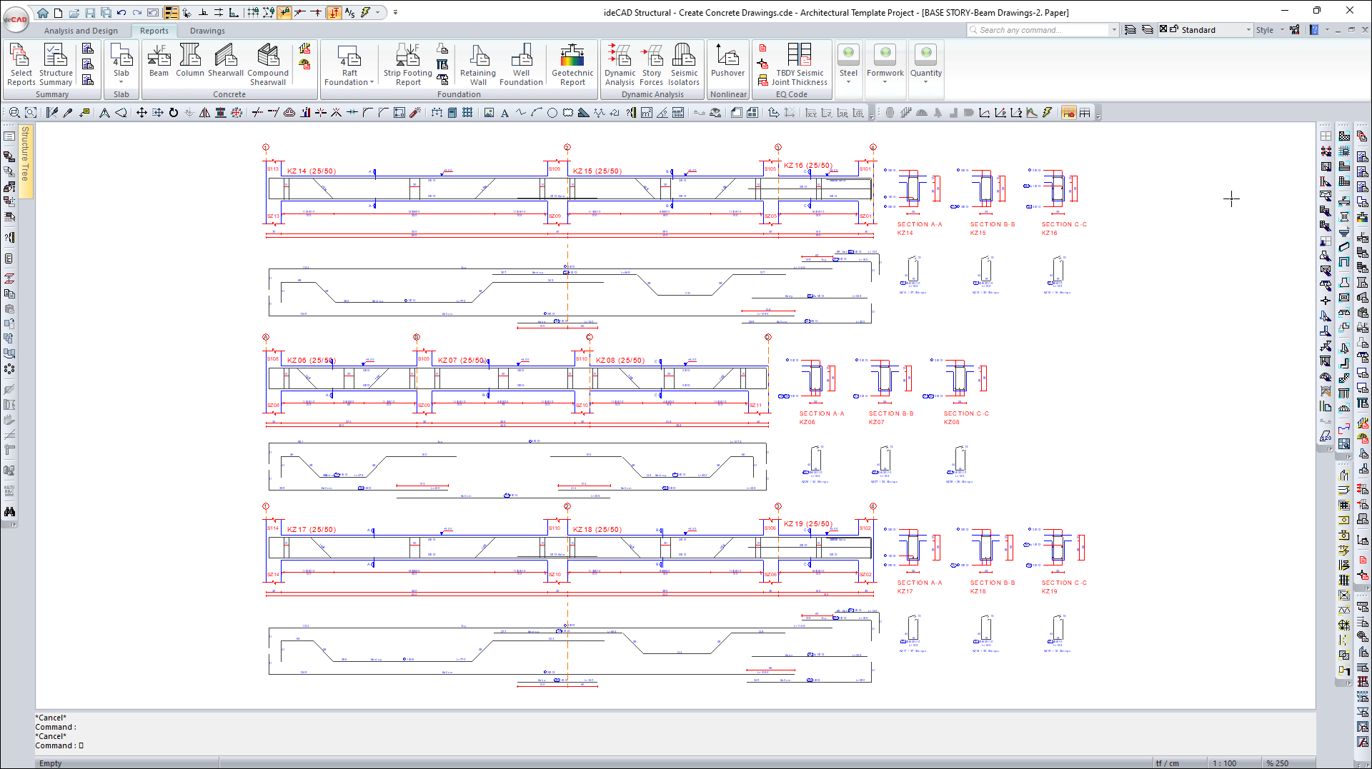
Beam Drawings will be created.
-
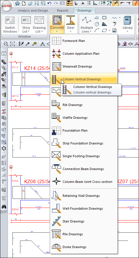
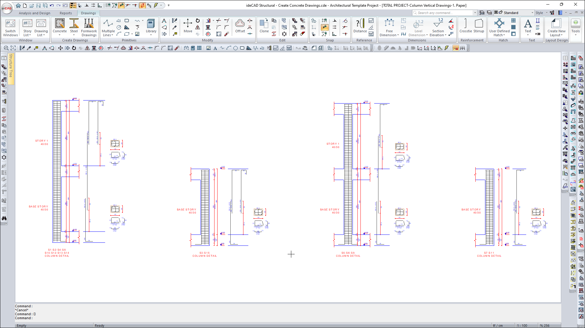
Click the Column Vertical Drawings command from the Concrete list.
-
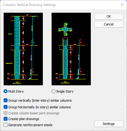
Click the OK button in the Column Vertical Concrete Drawings Settings dialog that opens.
-
For multi-story drawings, global type based numbering is applied information will be given.
-
Click the OK button to close the window.
-
Column Vertical Concrete Drawings will be created.
How to Create Concrete Drawings with ideCAD?
Follow the steps of the video below.
Next Tutorial