
The moment diagram and support deformations were examined according to 7 different loading conditions of a system consisting of three bars and the results of ideCAD Structural were compared.
Important Note: In this system solution, the effects of elongation and shear deformations are neglected for ease of manual solution. The cross-sectional area is multiplied by 1000 to neglect the elongation deformations, and the shear areas are defined as zero "0" to ignore the shear deformations.
|
Loading Status |
Node direction and number |
ideCAD Static |
Manual solution |
Percentage of error |
|---|---|---|---|---|
|
Condition 1 |
UZ (DN 4) (in) |
-0.02639 |
-0.02639 |
0% |
|
Condition 2 |
UZ (DN 4) (in) |
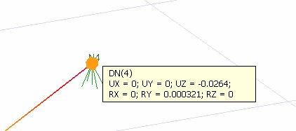
0.06296 |
0.06296 |
0% |
|
Condition 3 |
UZ (DN 4) (in) |
0.06296 |
0.06296 |
0% |
|
Condition 4 |
UZ (DN 4) (in) |
-0.29630 |
-0.29630 |
0% |
|
Condition 5 |
UX (D.N. 2) (in) |
0.31250 |
0.31250 |
0% |
|
Condition 6 |
UX (D.N. 2) (in) |
0.11556 |
0.11556 |
0% |
|
Condition 7 |
UX (D.N. 2) (in) |
0.00651 |
0.00651 |
0% |
Geometric Properties and System Description
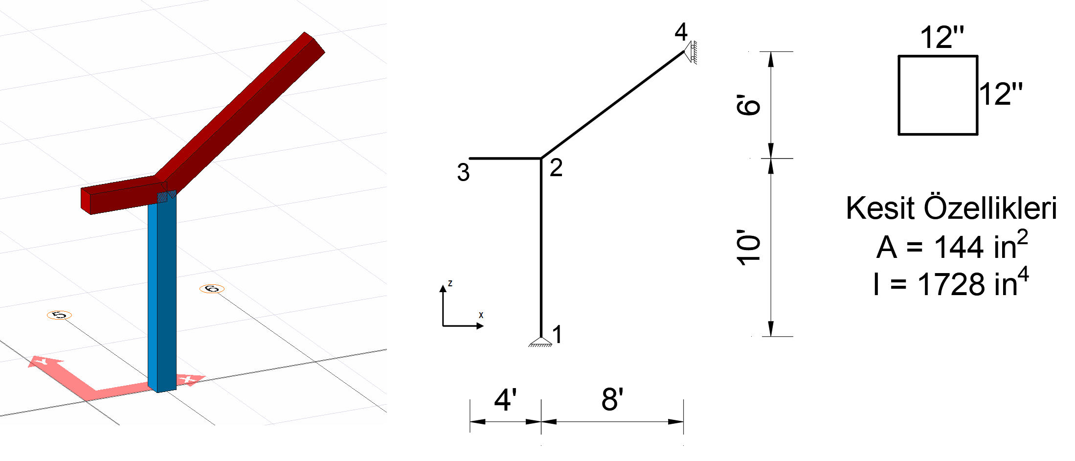
In the picture above, an isostatic system consisting of three rod elements is given. The horizontal distances are 4 ft and 8 ft, respectively, and the vertical distances are 10 ft and 6 ft, respectively. The fixed support is formed at joint number 1 and a movable support that can move in the Z axis direction at joint number 4.
A square section with a side of 12 inches is used as a rod element.
The area of the square section is calculated as A = 12 * 12 = 144 in 2 and the
moment of inertia I = (1/12) * (12 * 12 3 ) = 1728 in 4
. The modulus of elasticity of the material used was taken into account as E = 3600 k / in 2 and the unit volume weight as 0.15 k / ft 3 .
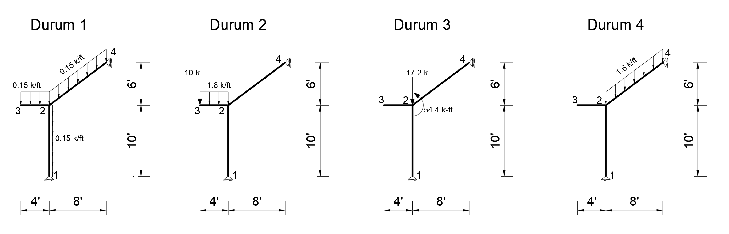
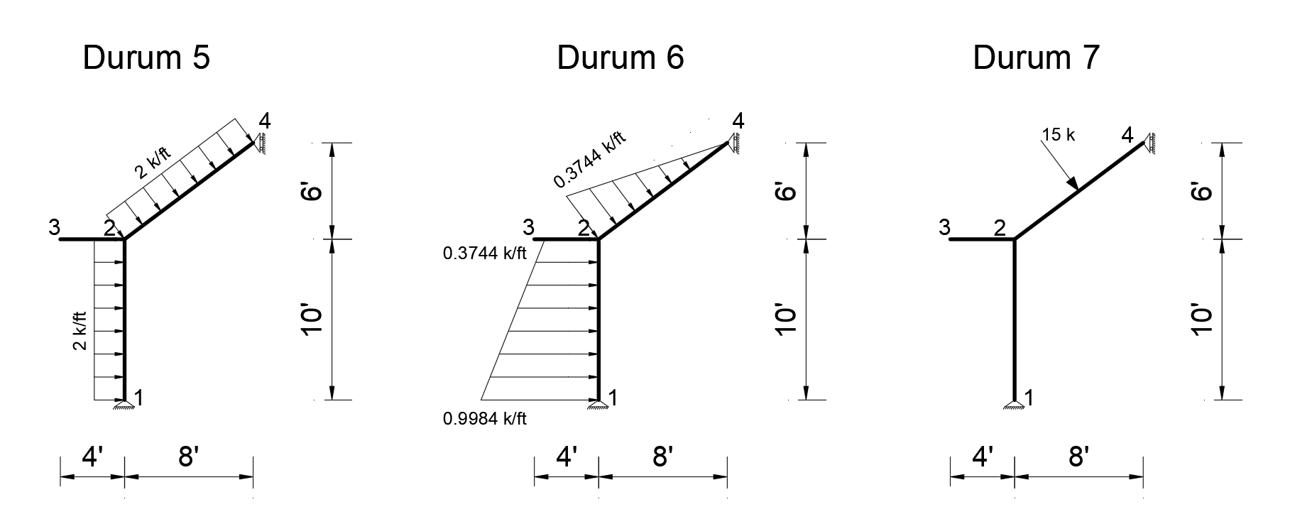
Loading situations
The following 7 loading cases have been defined for the above system. Of these loading cases, the deformation on the Z axis of joint 4 in Case1, Case2, Case3 and Case4, and the deformation on the X axis of joint point 2 in Case5, Case6 and Case7 were calculated. Virtual Work Method was used to find the deformations of nodes 2 and 4 .
You can reach the file with all loading statuses defined below.
izostatik 2D çerçeve genel yüklemeler.rar
Condition 1
In order to find the deformation in the Z axis of joint number 4, a unit force is applied to the system in the Z direction from only 4 joints and a bending moment diagram is drawn.
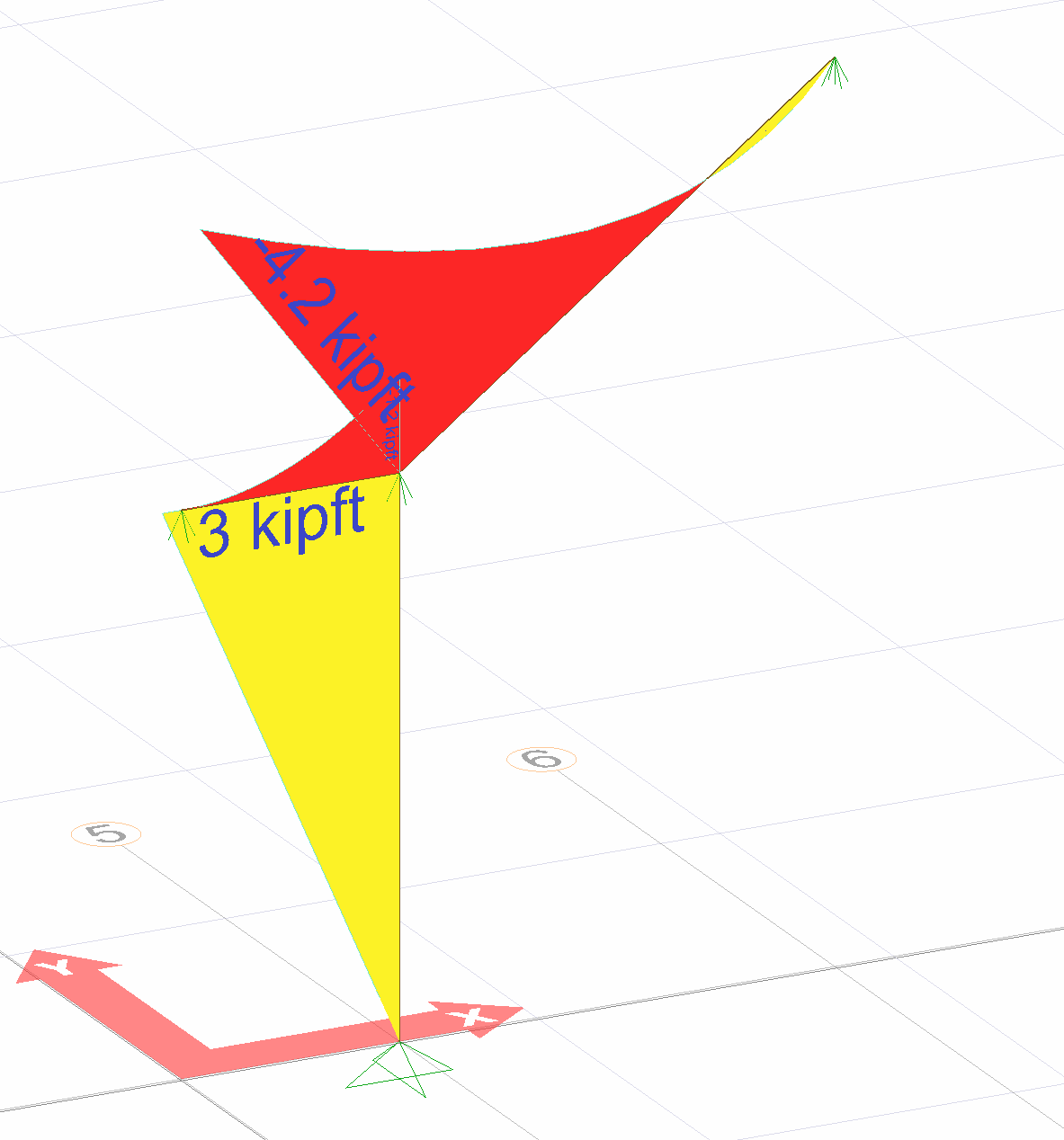
The image below shows the Status1 installation. In this system, 1 unit has been loaded in Z direction to joint point 4. Support reaction and moment diagram in this unit loading condition are shown.
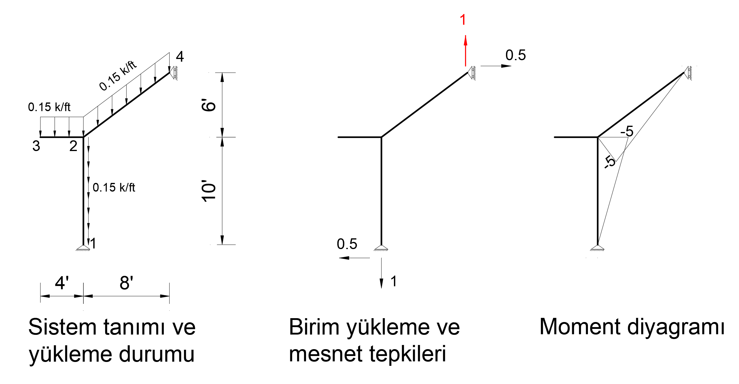
After the unit is loaded into the system, the support reaction and moment diagram created by the external loads in the system are given below.
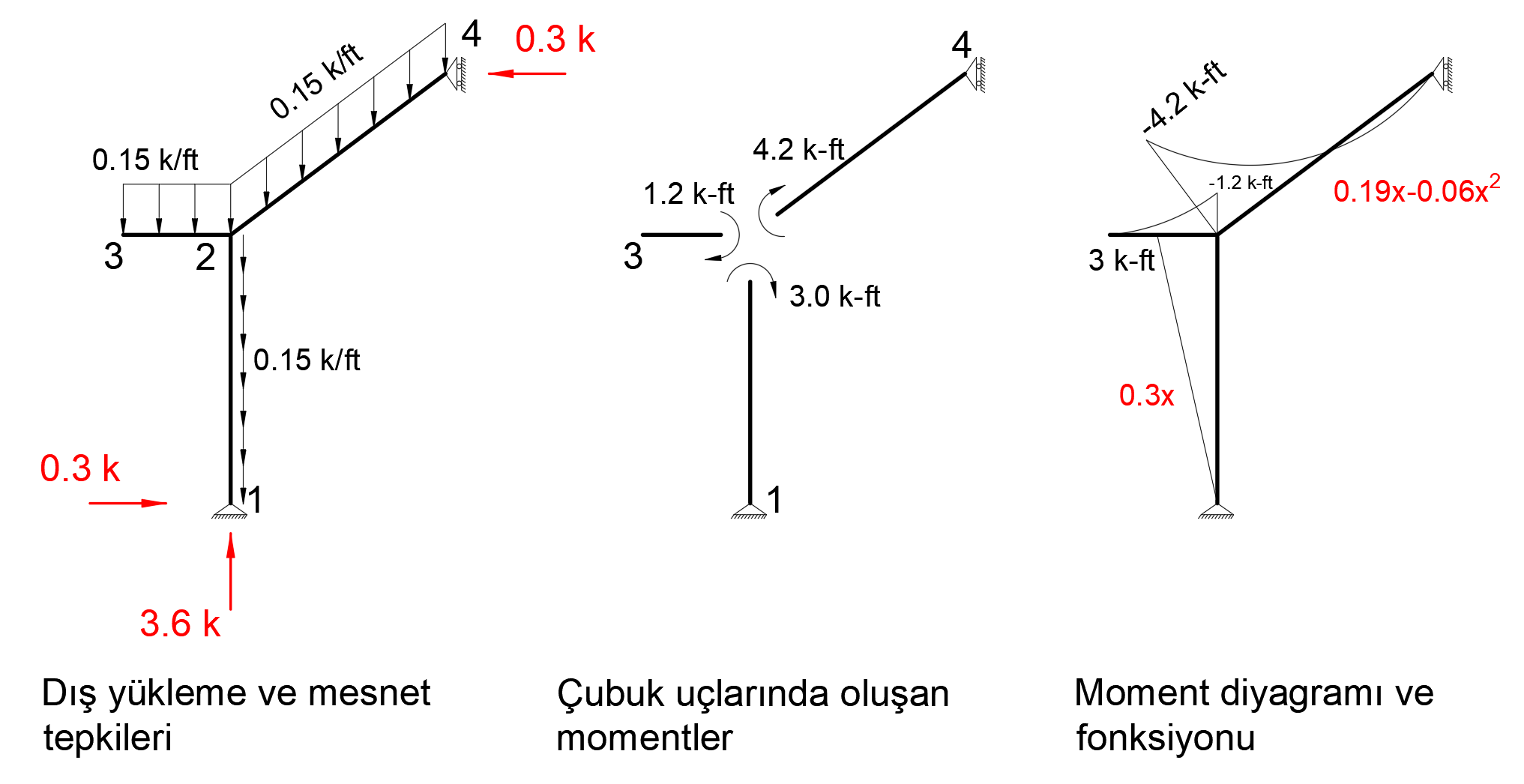
In the virtual work method, the moment diagram with unit loading, M 'and the moment diagram formed due to the normal loading of the system can be found by using the integral given below. In virtual work method, the following integral should be taken separately for all rods and its sign should be determined considering the moment direction.
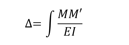
In this case, since the functions of the moment diagrams consisting of unit loading and external loads are known, the following integral can be written. In the first term of the integral below, it is computed for the bar between 1-2 nodes and in the second term for the bar between nodes 2-4.
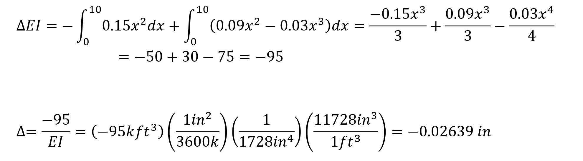
In this equation, unit represents the deformation at the point and direction of loading.
= -0.02639 is increased. This result is exactly the same with ideCAD Structural.
Condition 2
In order to find the deformation in the Z axis of joint number 4, a unit force is applied to the system in the Z direction from only 4 joints and a bending moment diagram is drawn.
The picture below shows the Status2 installation. In this system, 1 unit has been loaded in Z direction to joint point 4. Support reaction and moment diagram in this unit loading condition are shown.
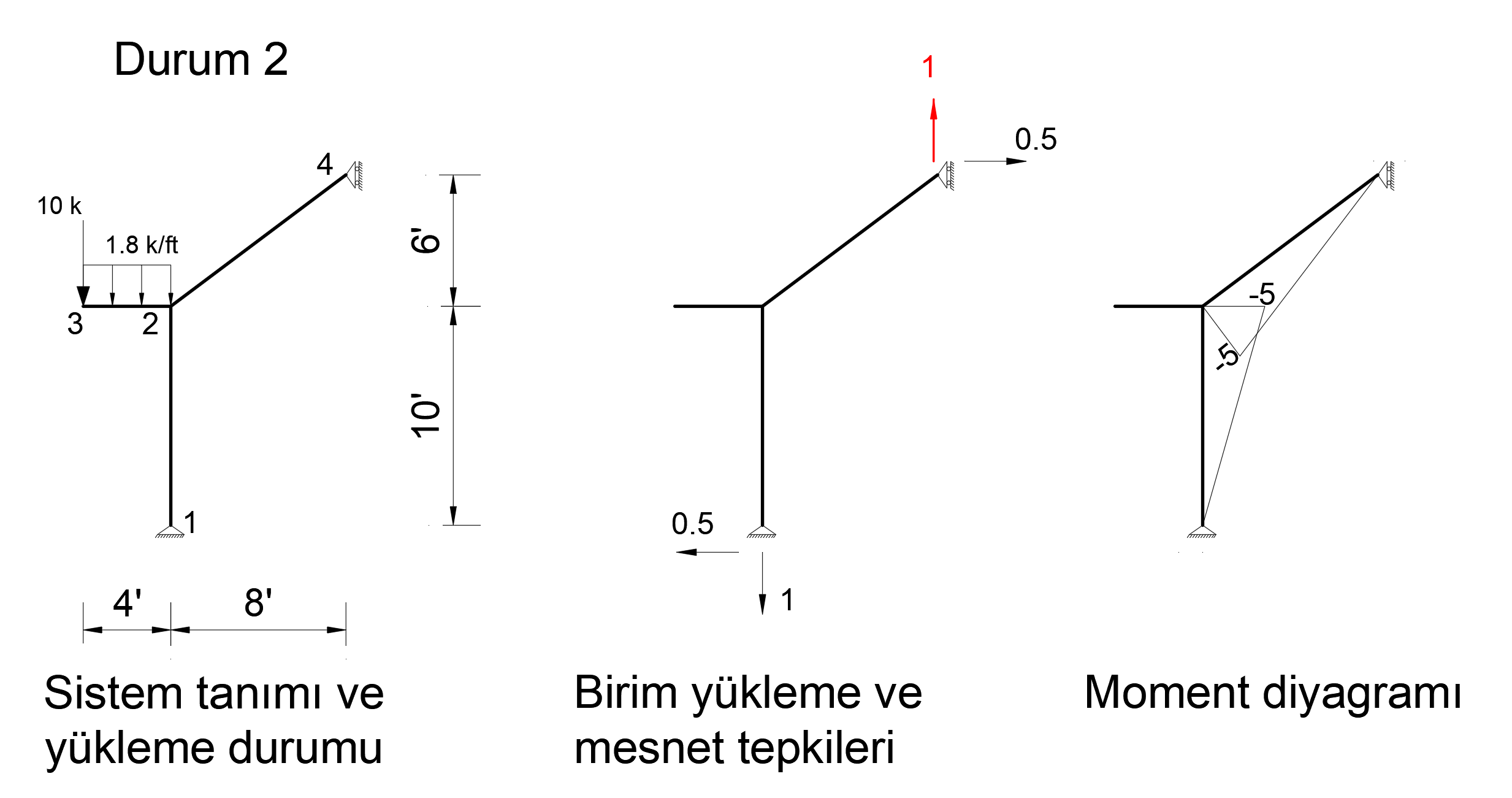
After the unit is loaded into the system, the support reaction and moment diagram created by the external loads in the system are given below.
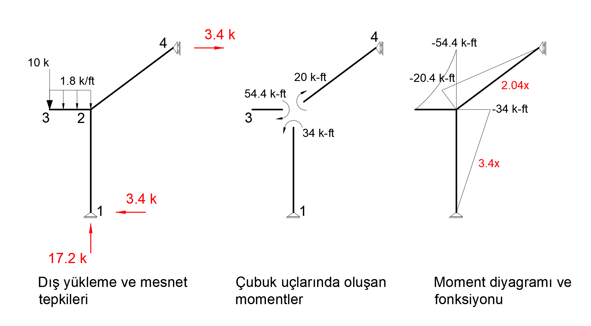
When virtual work is applied, the following equation becomes as follows.
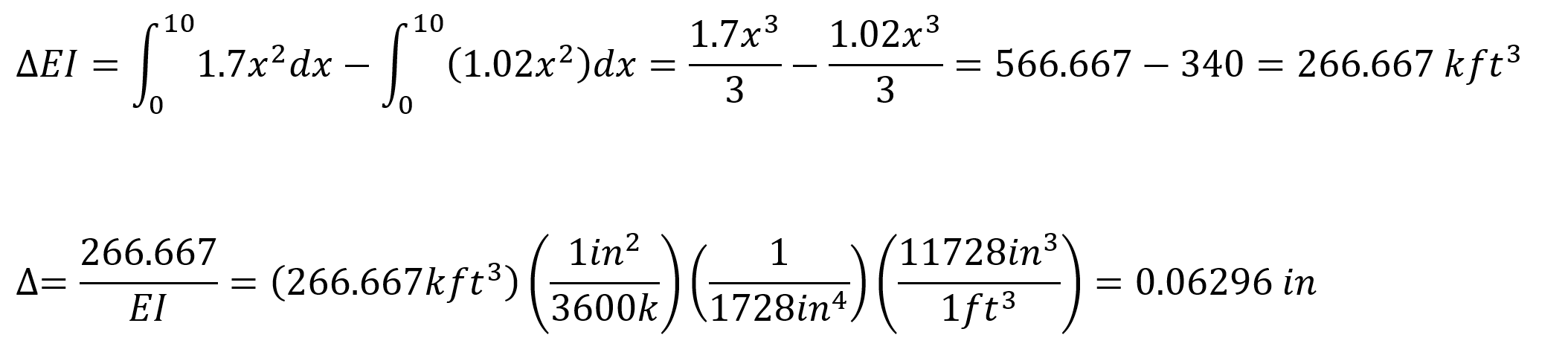
In this equation, unit represents the deformation at the point and direction of loading.
= 0.06296. This result is exactly the same with ideCAD Structural.
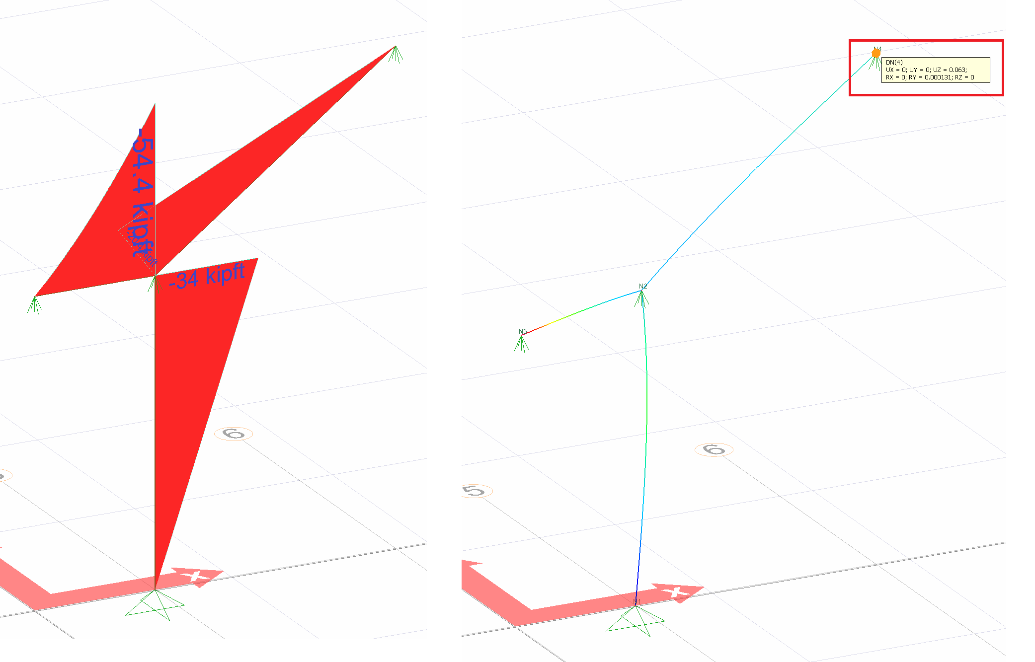
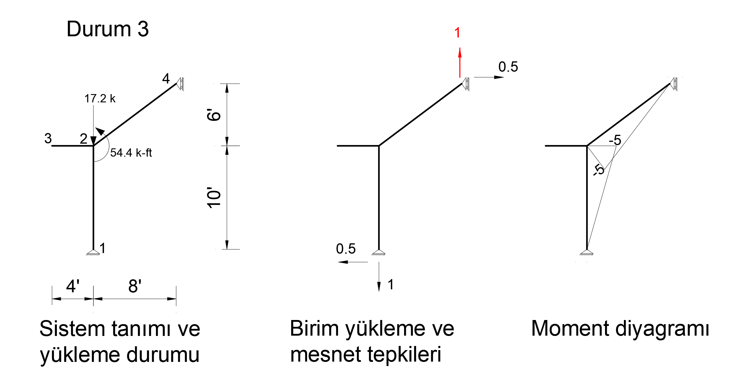
Condition 3
In order to find the deformation in the Z axis of joint number 4, a unit force is applied to the system in the Z direction from only 4 joints and a bending moment diagram is drawn.
The picture below shows the Status3 installation. In this system, 1 unit has been loaded in Z direction to joint point 4. Support reaction and moment diagram in this unit loading condition are shown.
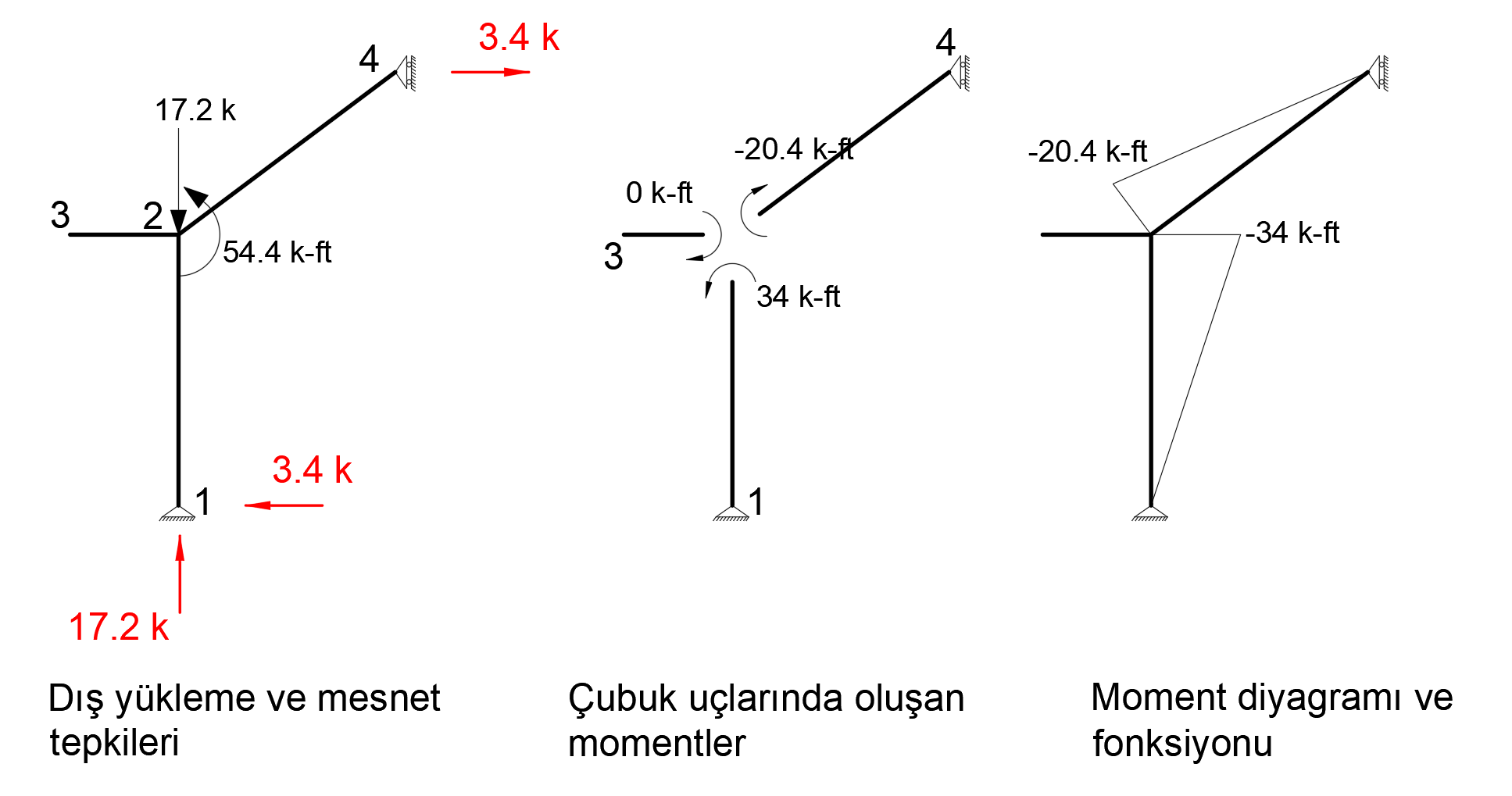
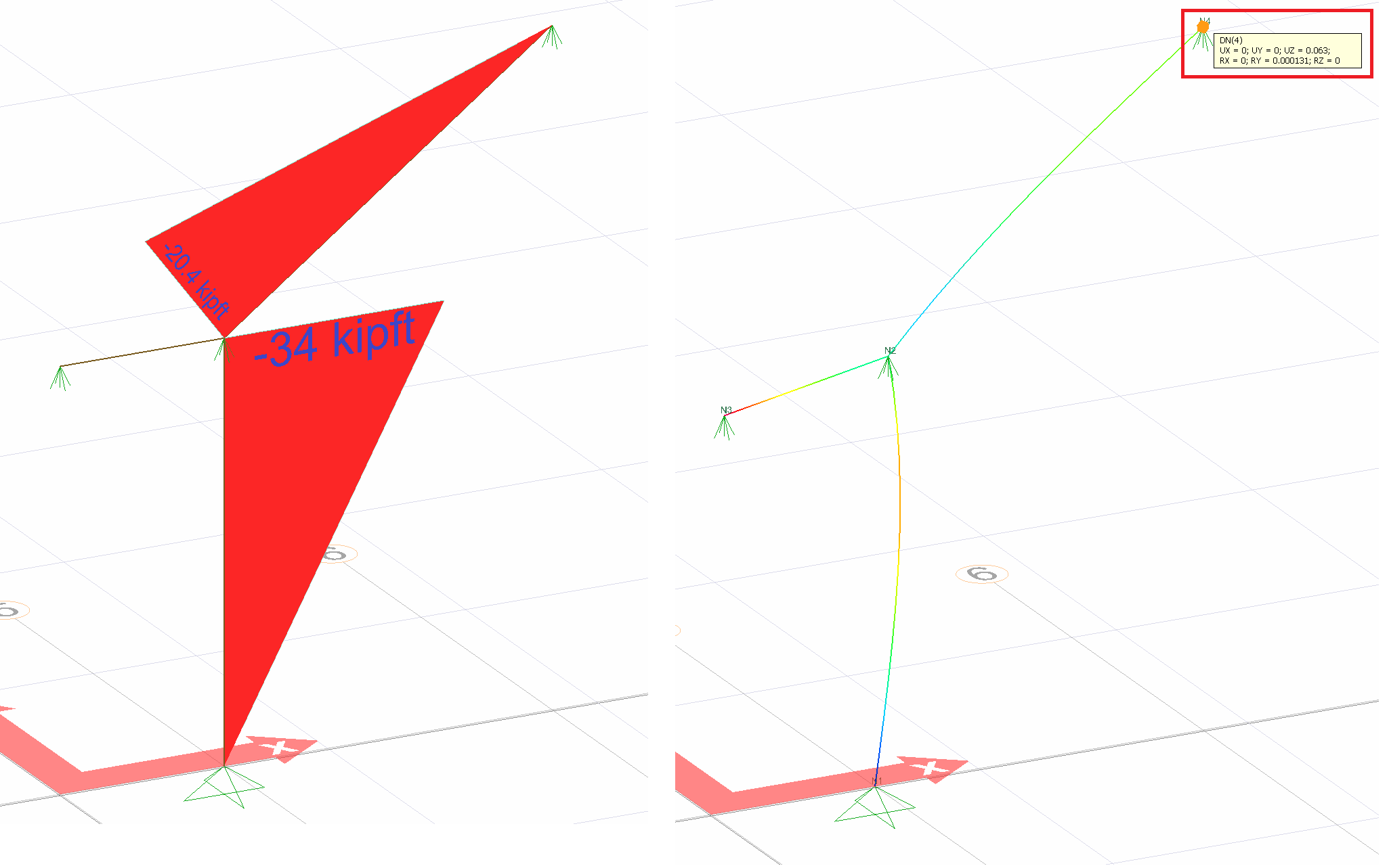
After the unit is loaded into the system, the support reaction and moment diagram created by the external loads in the system are given below.
When virtual work is applied, the following equation becomes as follows.
In this equation, unit represents the deformation at the point and direction of loading.
= 0.06296. This result is exactly the same with ideCAD Structural.
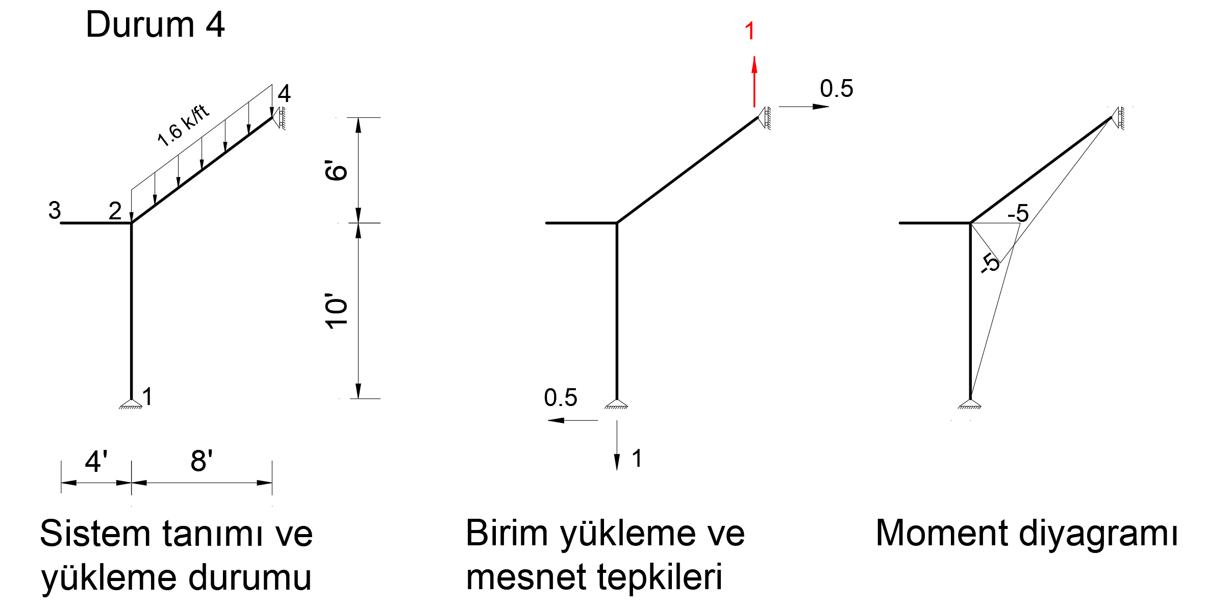
Condition 4
In order to find the deformation in the Z axis of joint number 4, a unit force is applied to the system in the Z direction from only 4 joints and a bending moment diagram is drawn.
The picture below shows the Status4 installation. In this system, 1 unit has been loaded in Z direction to joint point 4. Support reaction and moment diagram in this unit loading condition are shown.
After the unit is loaded into the system, the support reaction and moment diagram created by the external loads in the system are given below.
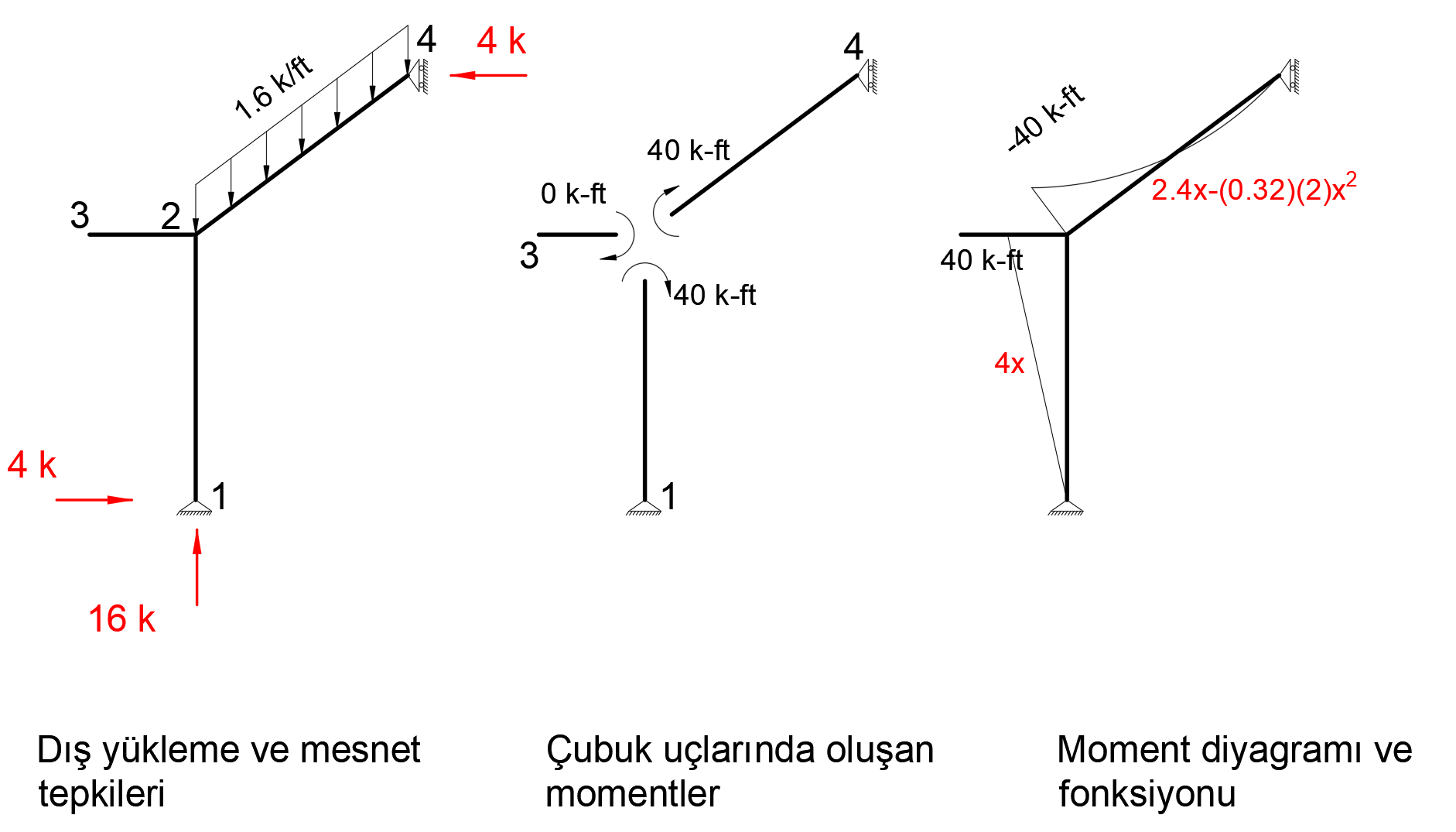
When virtual work is applied, the following equation becomes as follows.
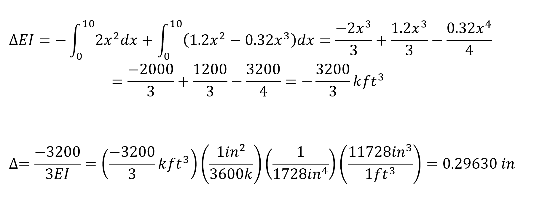
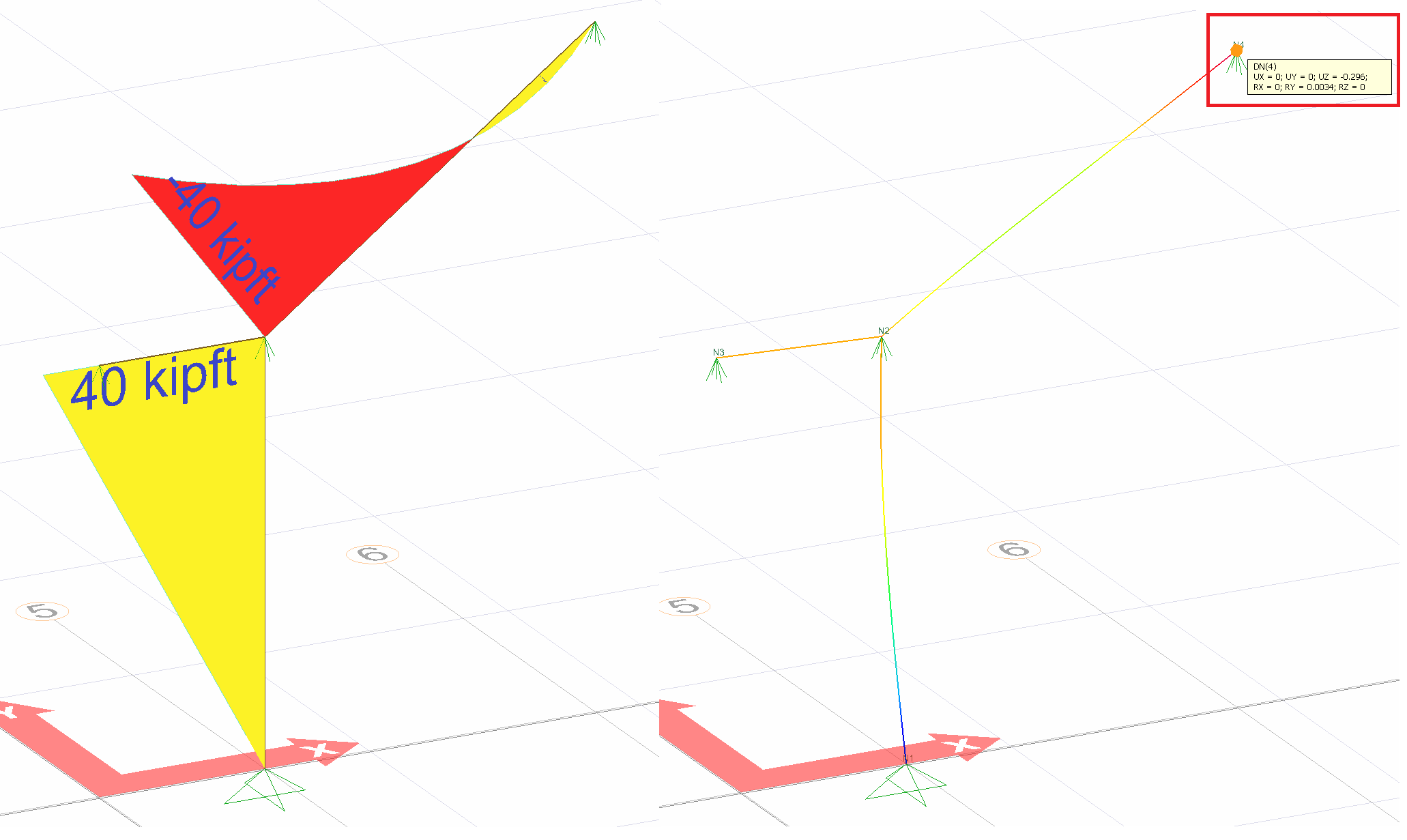
In this equation, unit represents the deformation at the point and direction of loading.
= -0.29630 is increased. This result is exactly the same with ideCAD Structural.
Condition 5
In order to find the deformation in the X axis of joint number 2, a unit force is applied to the system in the X direction from only 2 nodes and a bending moment diagram is drawn.
The image below shows the Status5 installation. In this system, 1 unit has been loaded in X direction to joint point 2. Support reaction and moment diagram in this unit loading condition are shown.
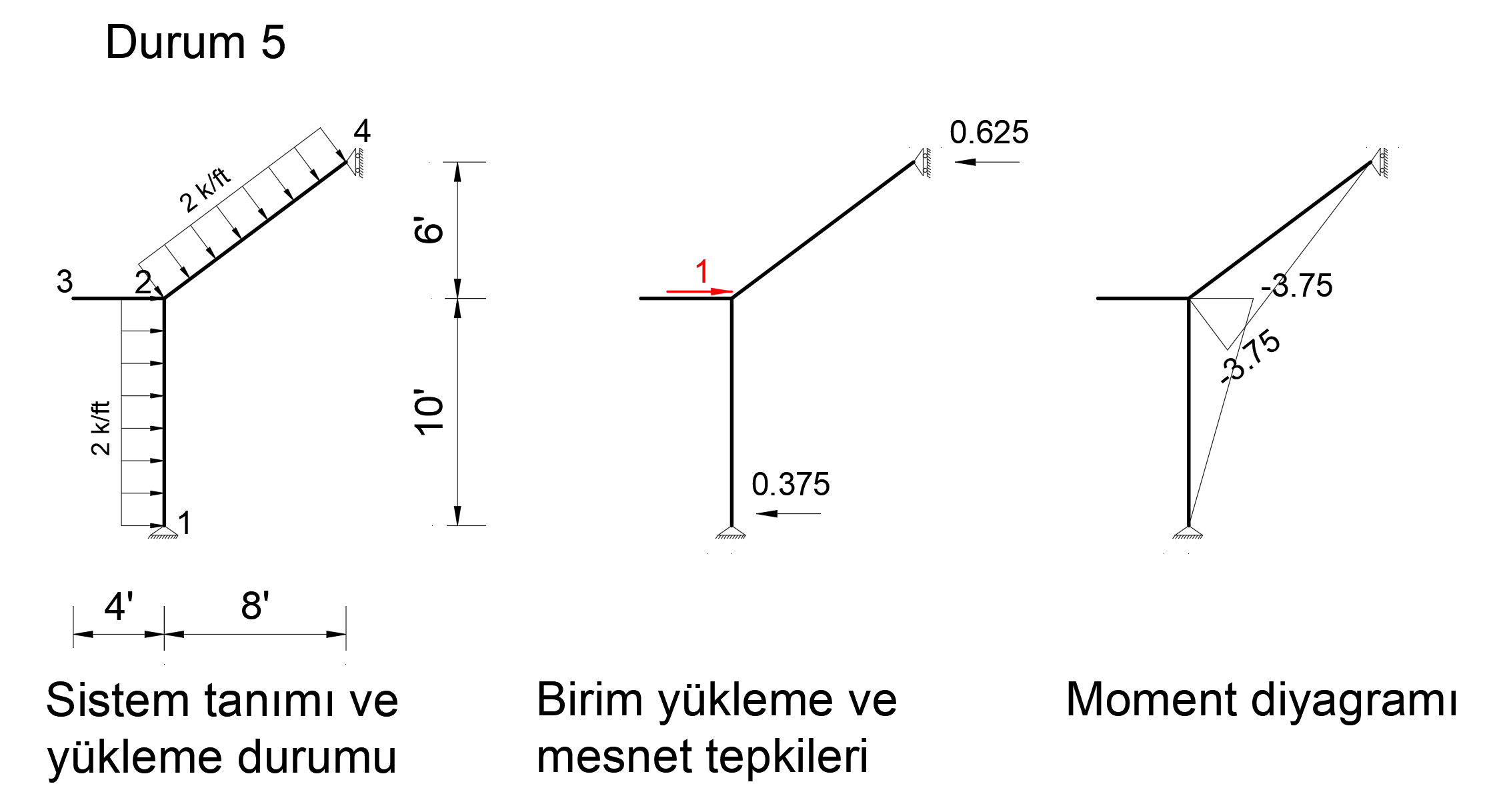
After the unit is loaded into the system, the support reaction and moment diagram created by the external loads in the system are given below.
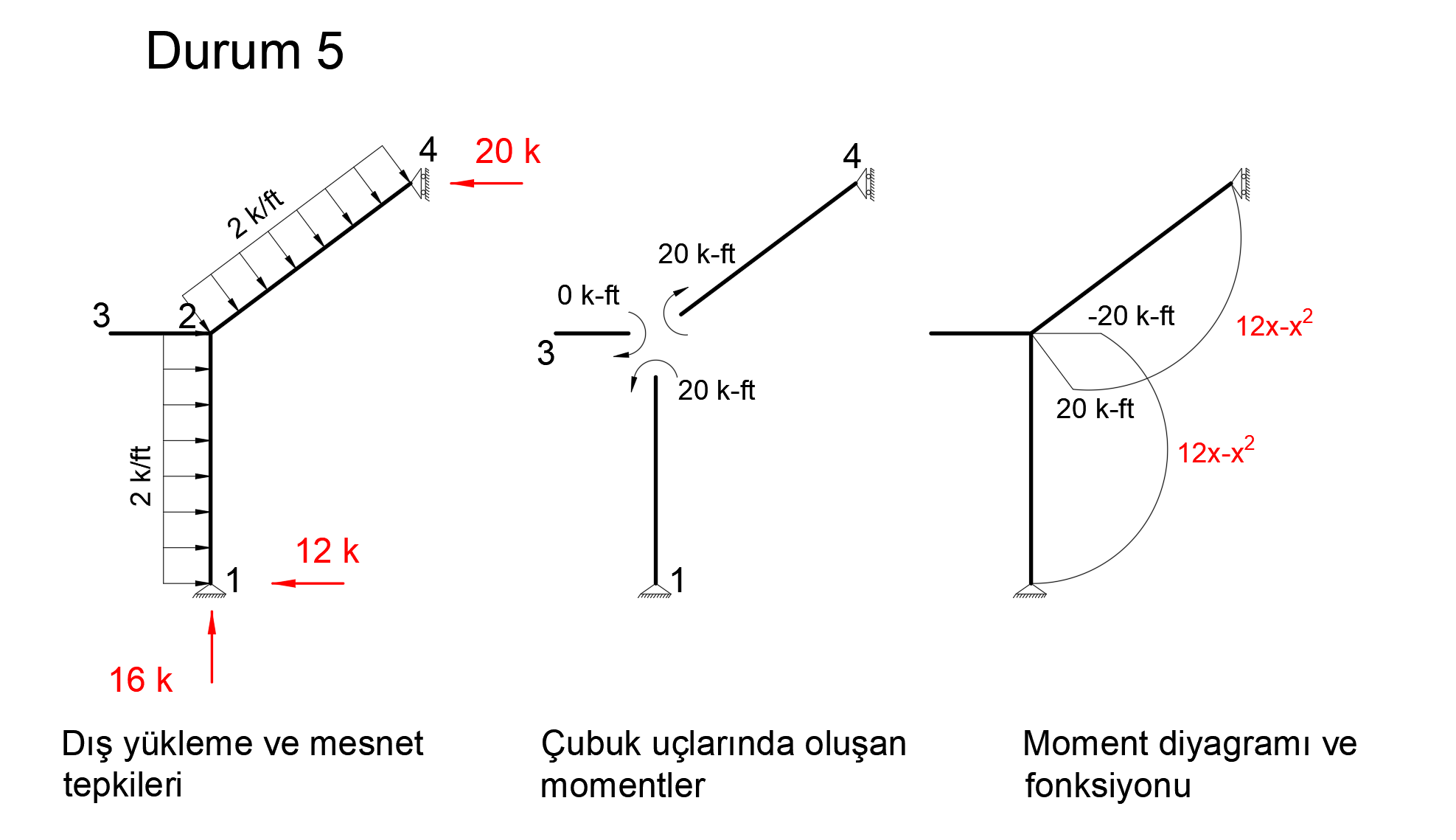
When virtual work is applied, the following equation becomes as follows.
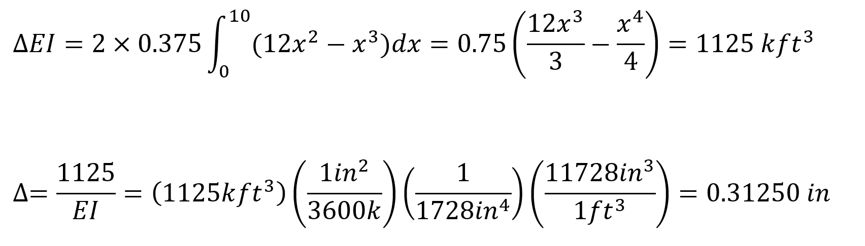
In this equation, unit represents the deformation at the point and direction of loading.
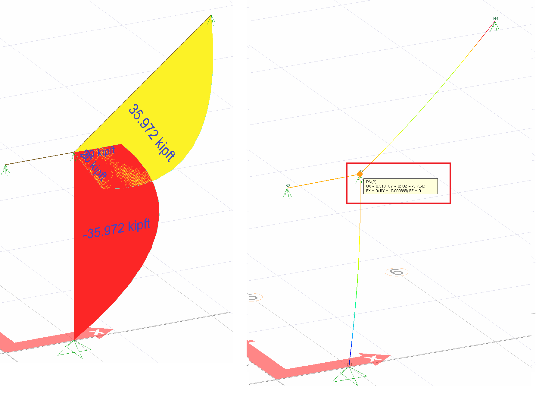
= 0.31250 in. This result is exactly the same with ideCAD Structural.
Condition 6
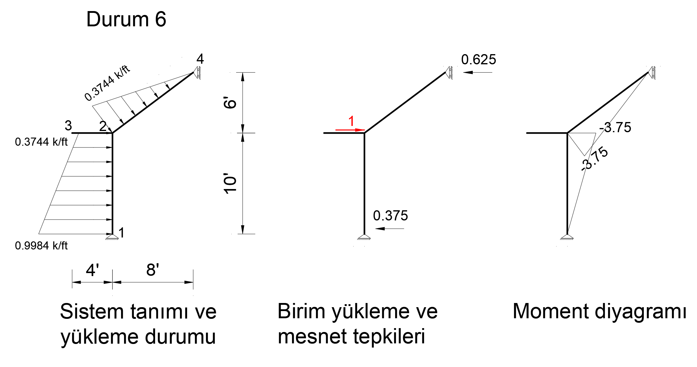
In order to find the deformation in the X axis of joint number 2, a unit force is applied to the system in the X direction from only 2 nodes and a bending moment diagram is drawn.
The picture below shows the Status6 installation. In this system, 1 unit has been loaded in X direction to joint point 2. Support reaction and moment diagram in this unit loading condition are shown.
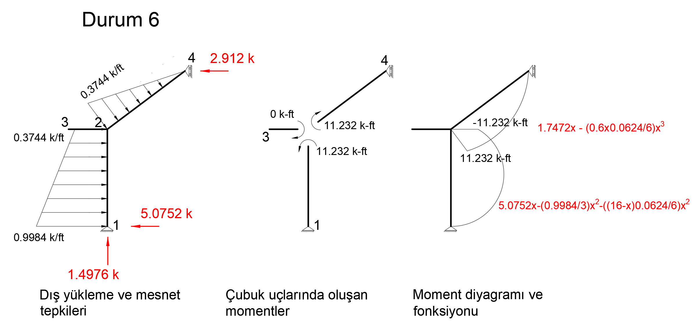
After the unit is loaded into the system, the support reaction and moment diagram created by the external loads in the system are given below.
When virtual work is applied, the following equation becomes as follows.
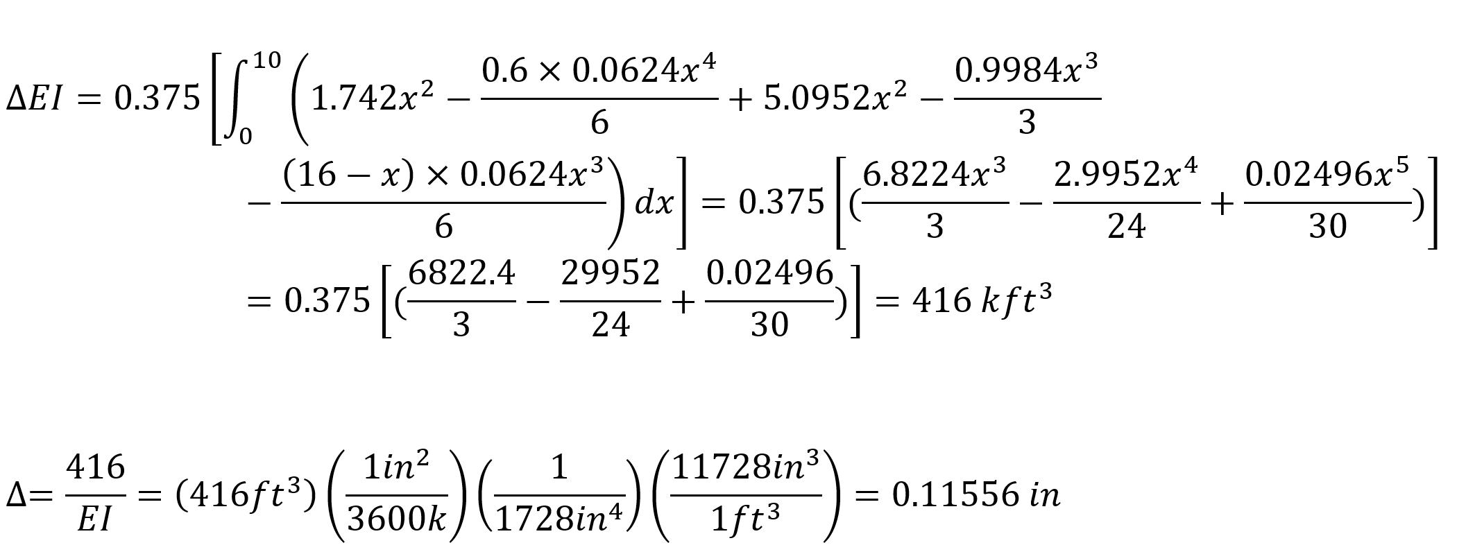
In this equation, unit represents the deformation at the point and direction of loading.
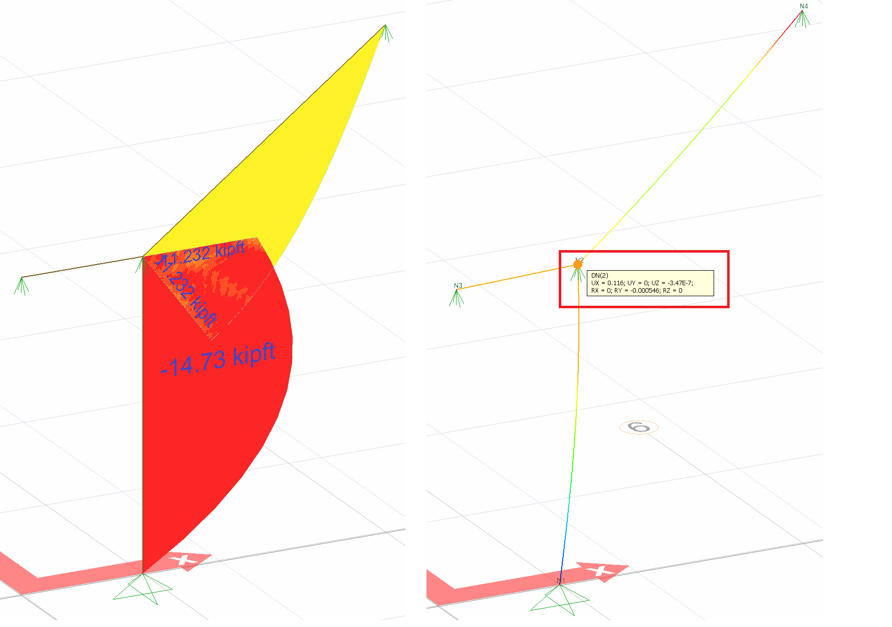
= 0.11556. This result is exactly the same with ideCAD Structural.
Condition 7
In order to find the deformation in the X axis of joint number 2, a unit force is applied to the system in the X direction from only 2 nodes and a bending moment diagram is drawn.
The picture below shows the Status7 installation. In this system, 1 unit has been loaded in X direction to joint point 2. Support reaction and moment diagram in this unit loading condition are shown.
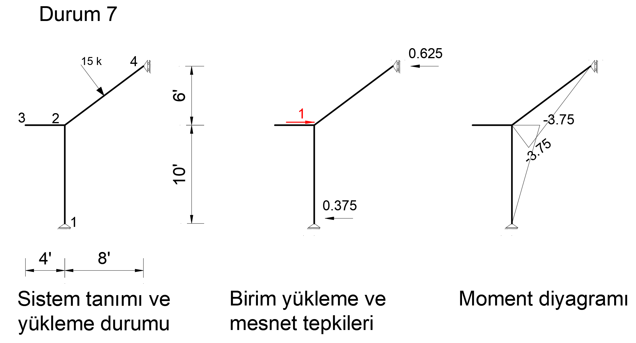
After the unit is loaded into the system, the support reaction and moment diagram created by the external loads in the system are given below.
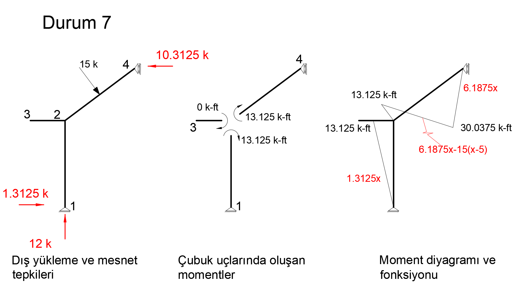
When virtual work is applied, the following equation becomes as follows.
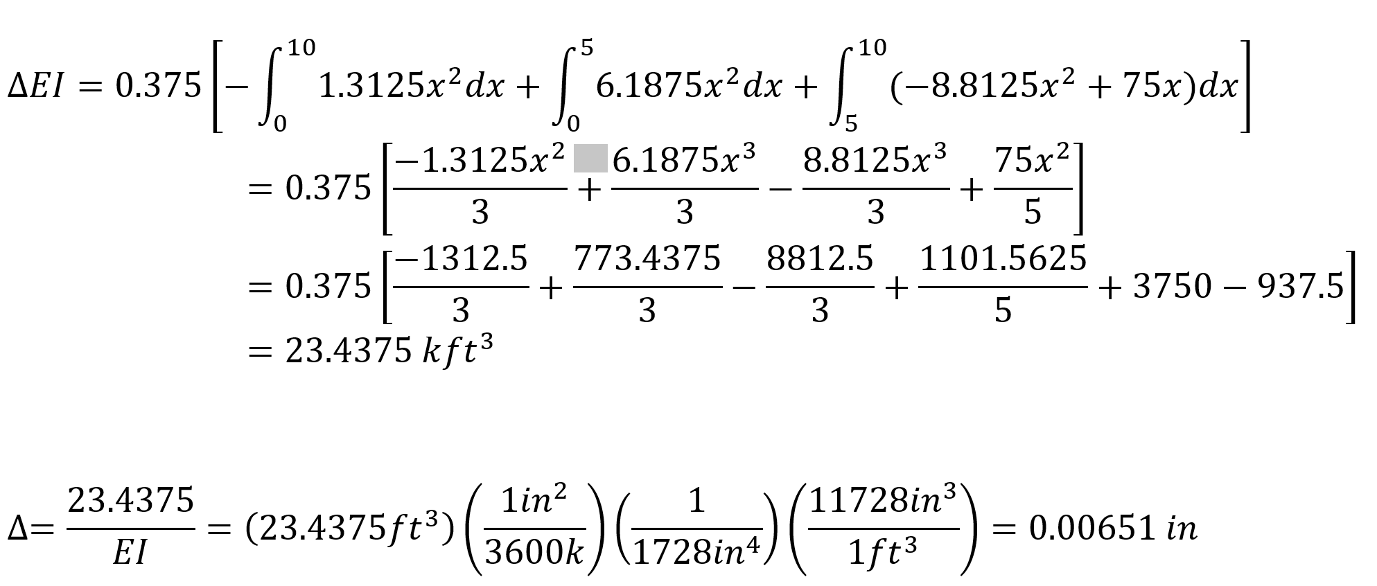
In this equation, unit represents the deformation at the point and direction of loading.
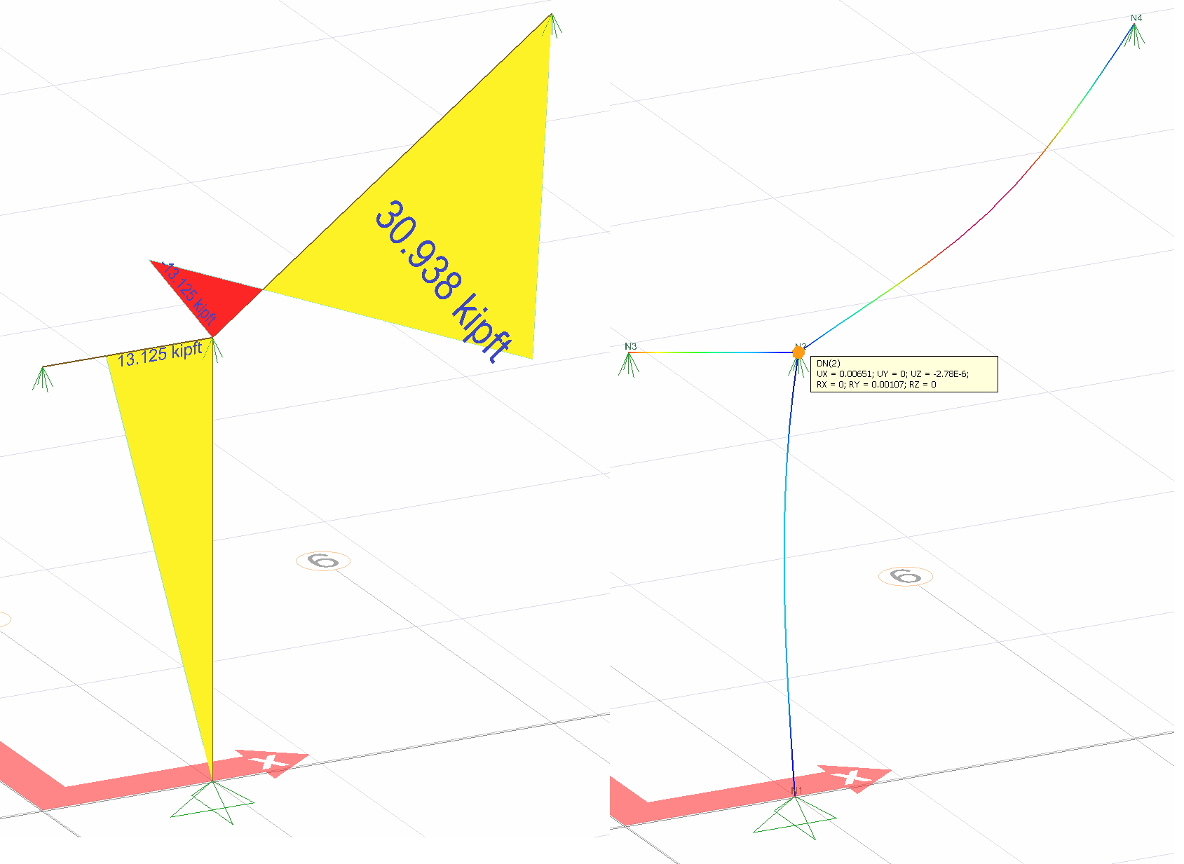
= 0.00651. This result is exactly the same with ideCAD Structural.
Next Topic