
How does ideCAD control beam-column flexural capacity ratios according to ACI 318-19?
-
For special moment frames, minimum flexural strength of columns are calculated automatically, aacording to ACI 18.7.3.
Download ideCAD for ACI 318-19
Notation
Ag = gross area of concrete section, in2
fc' = specified compressive strength of concrete, psi
fy = specified yield strength for nonprestressed reinforcement, psi
Mn = nominal flexural strength at section, in.-lb
Mnb = nominal flexural strength of beam including slab where in tension, framing into joint, in.-lb
Mnc = nominal flexural strength of column framing into joint, calculated for factored axial force, consistent with the direction of lateral forces considered, resulting in lowest flexural strength in.-lb
Mpr = probable flexural strength of members, with or without axial load, determined using the properties of the member at joint faces assuming a tensile stress in the longitudinal bars of at least 1.25fy and a strength reduction factor ϕ of 1.0, in.-lb
Pu = factored axial force; to be taken as positive for compression and negative for tension, lb
ϕ = strength reduction factor
The columns of special moment frames are considered part of the seismic-force resisting system. The subject of this title is to reduce the possibility of yielding in columns of special moment frames. Columns not stronger than beams increased the likelihood of inelastic action. The worst possible case is when all columns in a given story have flexural yielding at both ends. In this case, it creates a column failure mechanism to cause collapse. In order to avoid this situation, the minimum flexural strength of column control given in ACI 18.7.3 should be satisfied.
The flexural strengths of the columns shall satisfy ACI Eq.(18.7.3.2),
ΣMnc is the sum of nominal flexural strengths of columns framing into the joint. Column flexural strength is calculated for the factored axial load, Pu, consistent with the direction of the lateral forces considered, resulting in the lowest flexural strength.
ΣMnb is the sum of nominal flexural strengths of the beams framing into the joint, evaluated at the faces of the joint.
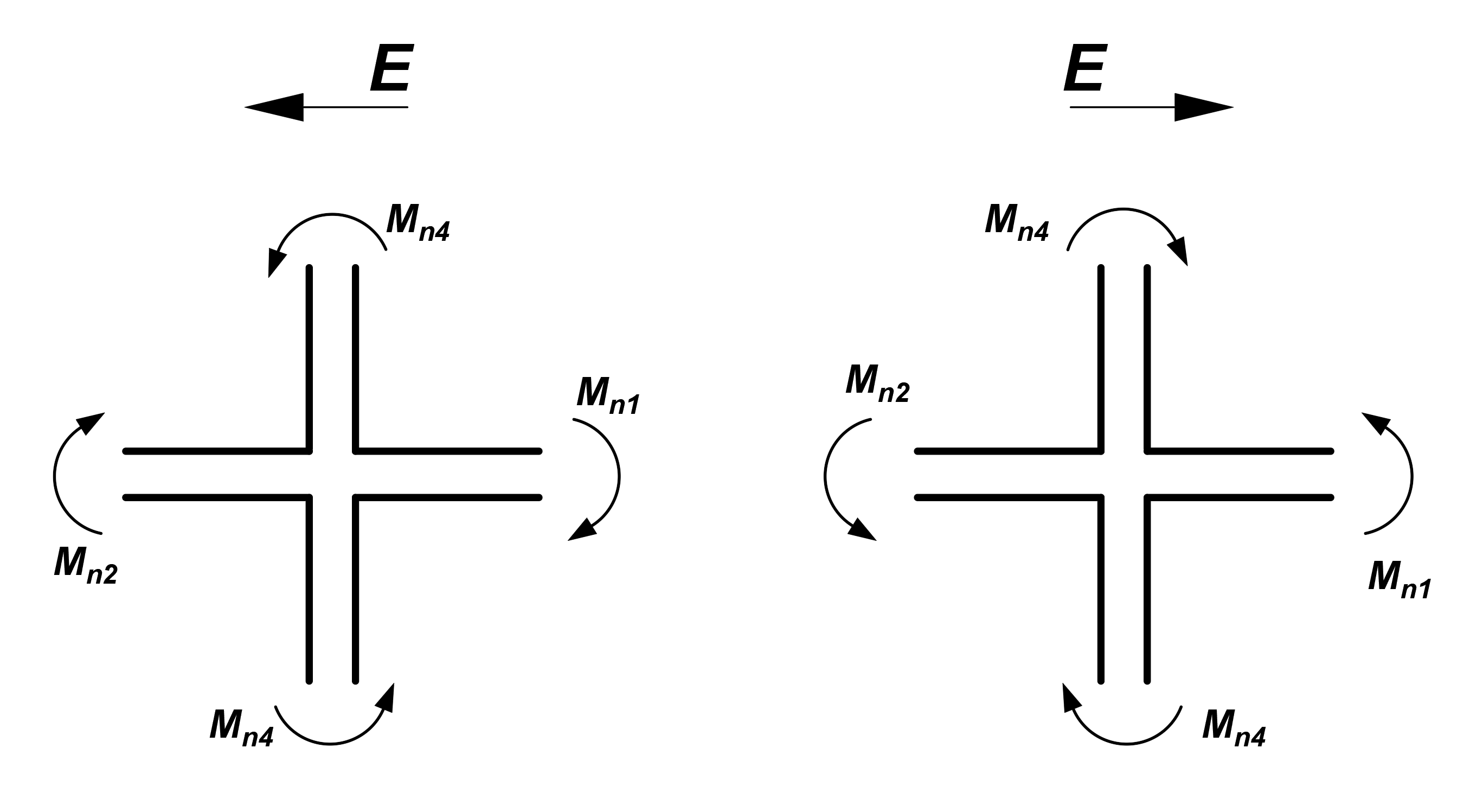
The obtaining of ΣMnc and ΣMnb values are shown below for both directions.
-
ΣMnc = Mn4 + Mn3
-
ΣMnb = Mn2 + Mn1
The factored axial force, Pu, in each column is calculated from the program for each load combination. For each design load combination, the moment capacity of each column under the unfilence of axial load is then determined separately for the major and minor directions of the column, using the three-dimensional interaction failure surface.
The Mn values used in the calculation of ΣMnc and ΣMnb values are the nominal flexural strengths described in the Flexural Strength per ACI 318-19 with ideCAD and Axial strength or Combined Flexural and Axial Strength per ACI 318-19 with ideCAD titles. Nominal flexural strength Mn, is calculated without using the strength reduction factor (ϕ=1) and as the reinforcement yield stress fy. Mn is shown by the green curve in the graph above.
Columns should satisfy ACI Eq.(18.7.3.2), except for the two cases given below.
-
Connections where the column is discontinuous above the connection.
-
Column factored axial compressive force, Pu under load combination including earthquake effect, E are less than Agfc' /10.