
Defined sections are created with the Create Custom Section command in the Sections row in the structure tree . In the Section Settings window, geometric properties such as width, length and thickness, material and values such as moment of inertia and cross-sectional area of the sections to be defined are entered.
Location of the Create Custom Section Command
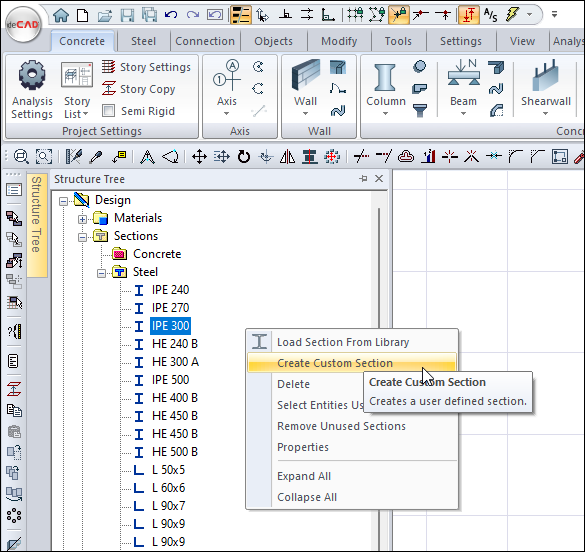
You can access the Create Custom Section command from the Steel line in the Sections section of the structure tree.
Usage Steps - Making a Rolled I Single Type
-
Click the Create Custom Section command.
-
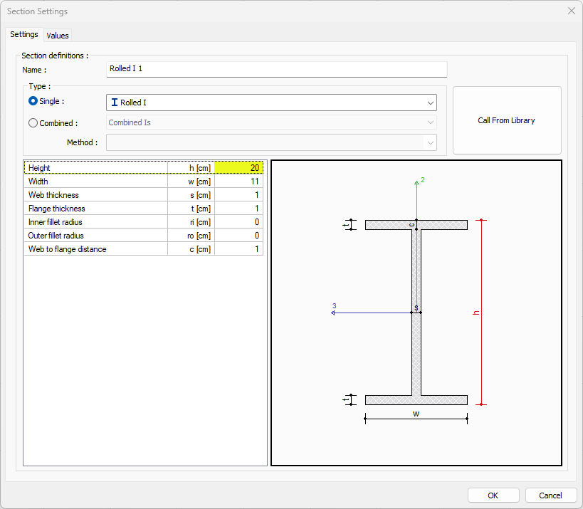
In the dialog that opens, select the Single option.
-
Select the Rolled I profile from the list .
-
Enter geometric properties.
-
When you click the OK button, the section you defined will be added to the structure tree.
|
Usage step |
|---|
|
Checking the Single option and selecting the Rolled I profile from the list 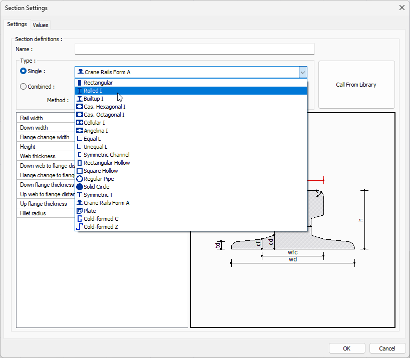
|
|
Entering geometric features 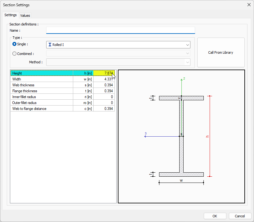
|
Usage Steps - Creating Twice Spliced Combined Is Type
-
Click the Create Custom Section command.
-
In the dialog that opens, check the Combined option.
-
Enter a name for the newly defined section.
-
Select the Combined I row from the list .
-
Select Twice Spliced from the method list .
-
The Combined Section dialog will open.
-
Select the profile type for the section from the list.
-
Close the dialog by clicking OK.
-
Determine the distance between sections.
-
When you click the OK button, the section you defined will be added to the structure tree.
|
Usage step |
|---|
|
Checking the Combined option and selecting the Combined I profile from the list 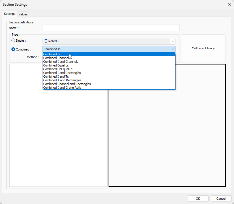
|
|
Choosing Twice Spliced as the method 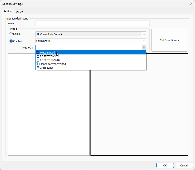
|
|
Selecting a profile for the section from the combined sections dialog 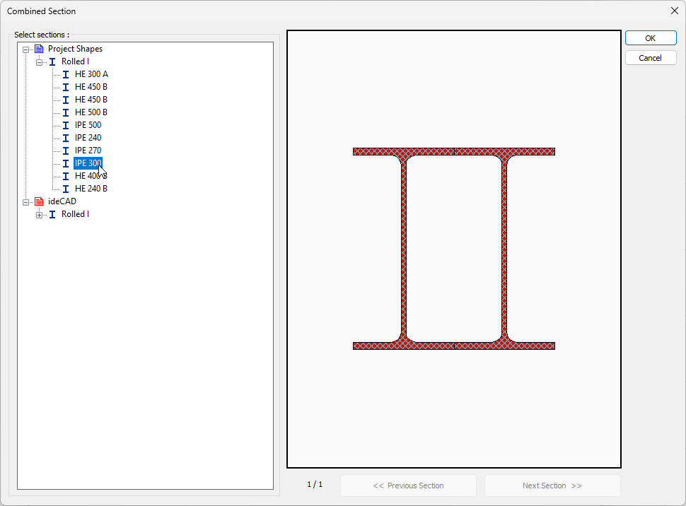
|
|
Determining the distance between sections 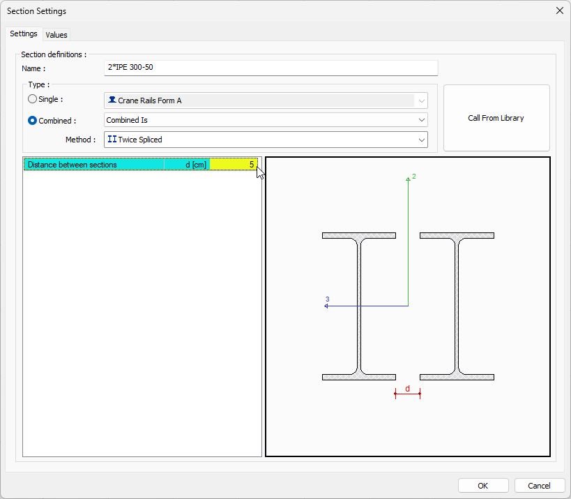
|
Section Settings Dialog Settings Tab
|
Specifications |
|---|
|
Name Name of the section. |
|
Single (Profile Type) 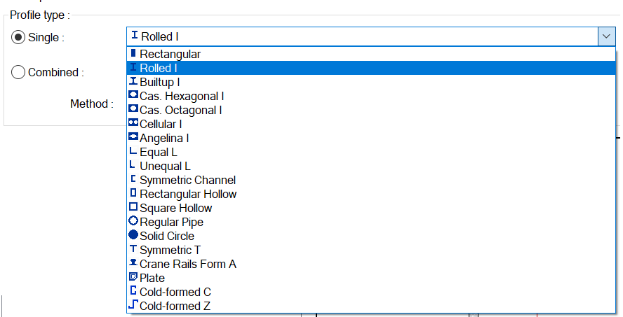
The type to be defined is determined. When this option is selected and from the list, the cross-section type used to be a uniform cross-section (rectangular, rounds, I, C...) |
|
Combined (Profile Type) 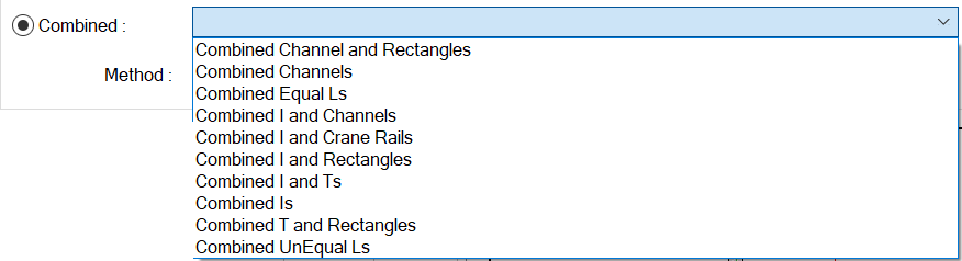
The type to be defined is determined. They are cross-sections created by combining in many different ways (double L, double U-section…) when preferred in this option and in the cross-section type used from the list. |
|
Method 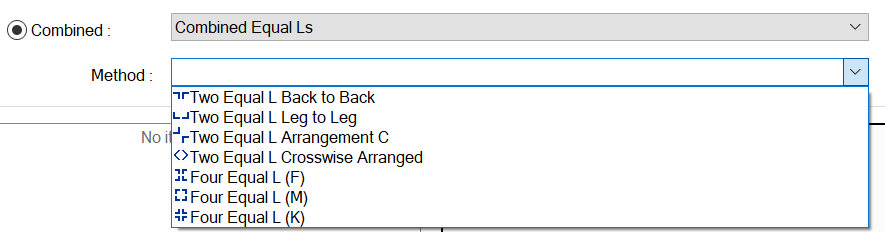
In the case of displaying in the combined type, the method of combining different segments is determined. |
|
Geometric Features 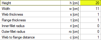
This is the section where the selected section type is detailed. It shows according to each section type. |
|
Preview 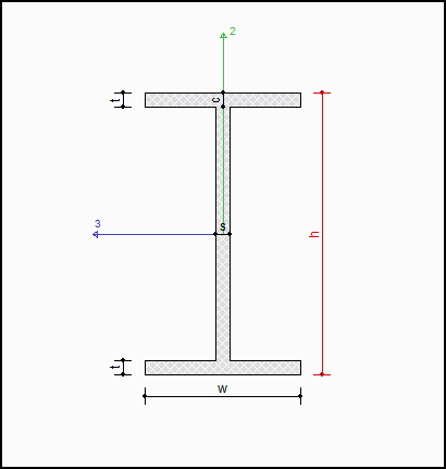
It is done concurrently, which should be considered as Restricted. |
|
Call from library 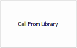
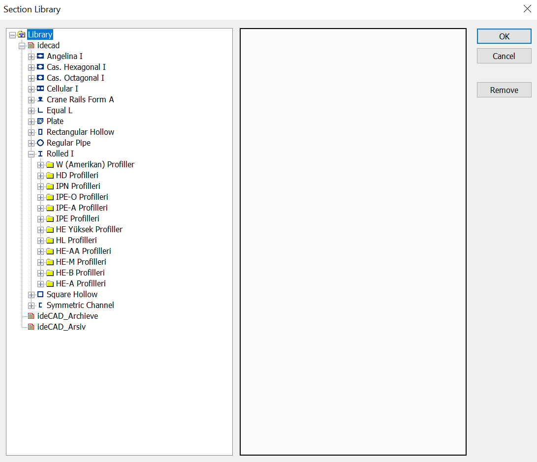
It brings the properties of a section selected from the section library to the window. |
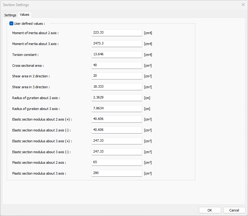
Section Settings Dialog Values Tab
|
Features |
|---|
|
User Defined Values When checked, it allows to change the cross-section properties of the section. |
|
Moment of inertia about 2 axles It is the moment of inertia of the section about the 2-2 axis. |
|
Moment of inertia about 3 axis It is the moment of inertia of the section about the 3-3 axis. |
|
Torsional Constant It is the torsional moment of inertia of the section. |
|
Cross-sectional area Cross sectional area of the section |
|
Shear area in 2 directions It is the shear area in the 2-2 direction of the section. |
|
Shear area in 3 direction It is the shear area in the 3-3 direction of the section. |
|
Radius of gyration about 2 axis It is the radius of gyration about the 2-2 axis. |
|
Radius of gyration about 3 axis It is the radius of gyration about the 3-3 axis. |
|
Elastic section modulus about 2 axis ( + ) It is the Elastic section modulus about the 2-2 axis and in the positive direction. |
|
Elastic section modulus about 2 axis ( - ) It is the Elastic section modulus about the 2-2 axis and in the negative direction. |
|
Elastic section modulus about 3 axis ( + ) It is the Elastic section modulus about the 3-3 axis and in the positive direction. |
|
Elastic section modulus about 3 axis ( - ) It is the Elastic section modulus about the 3-3 axis and in the negative direction. |
|
Plastic section modulus about 2 axis It is the plastic section modulus about the 2-2 axis and in the negative direction. |
|
Plastic section modulus about 3 axis It is the plastic section modulus about the 3-3 axis and in the negative direction. |
The 2 and 3 axes are specified in the preview in the Settings tab.
Next Topic