
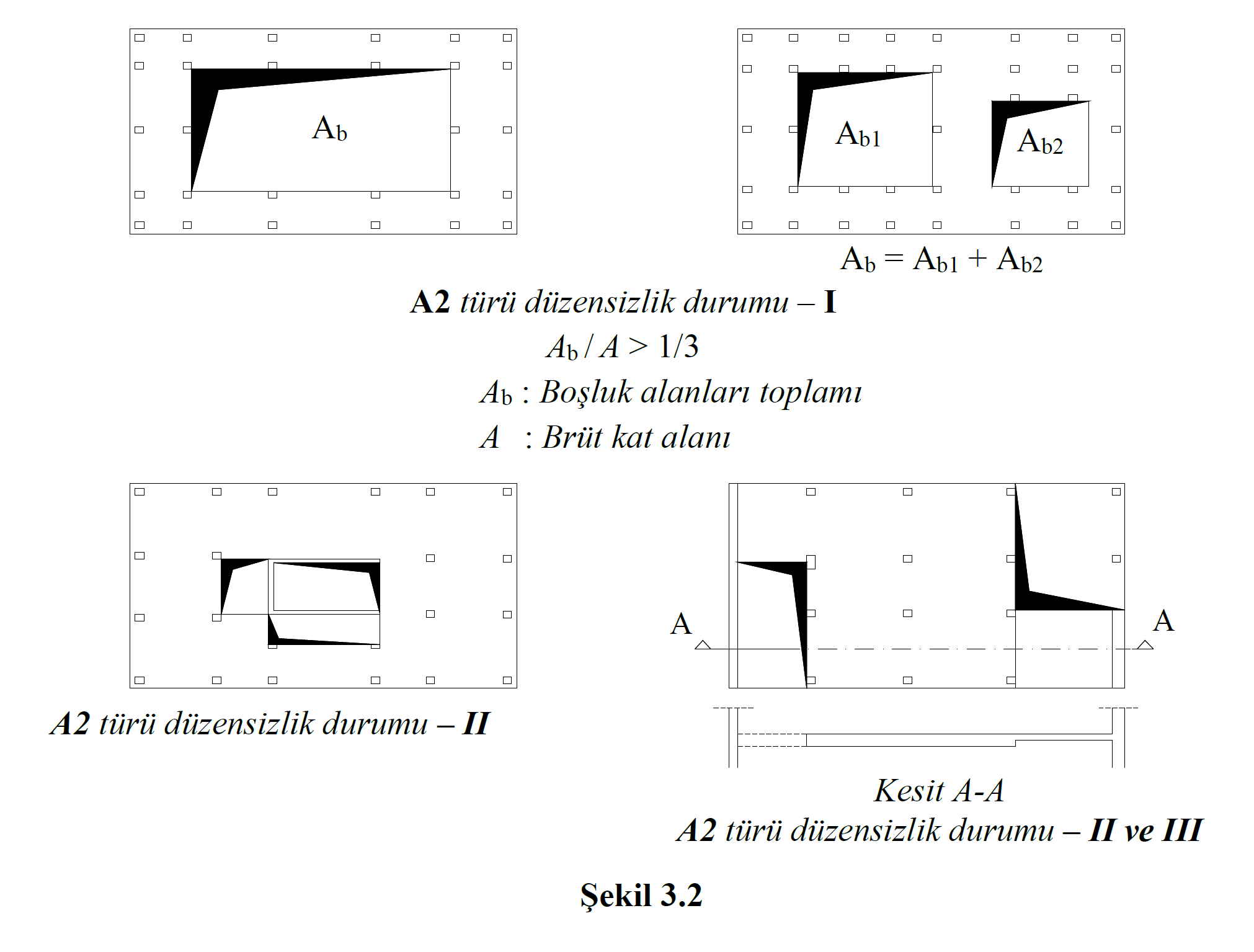
ICONS
A = Gross floor area
A b = Total void areas
A2 - Floor Discontinuities: In any floor slab (Figure 3.2) ;
I - Including stairs and elevator shafts, the total of void areas exceeding 1/3 of the floor gross area,
II - The presence of local floor gaps that make it difficult to safely transfer earthquake loads to vertical bearing system elements,
III - Sudden decreases in the in-plane rigidity and strength of the floor in case of
TBDY Article 3.6.2.2 - In buildings with A2 and A3 type irregularities, floor slabs will be modeled with two-dimensional plate (membrane) or shell finite elements to show that they can safely transfer earthquake forces between vertical bearing system elements in their own planes (See 4.5.6.2 ).
According to Article 4.5.6.2 - 3.6.2.2 of TBDY , in buildings where there are A2 and A3 type irregularities and / or floors are not intended to operate as a rigid diaphragm , and in slab systems without reinforced concrete beams, floors will be modeled with two-dimensional finite elements.
Next Topic