
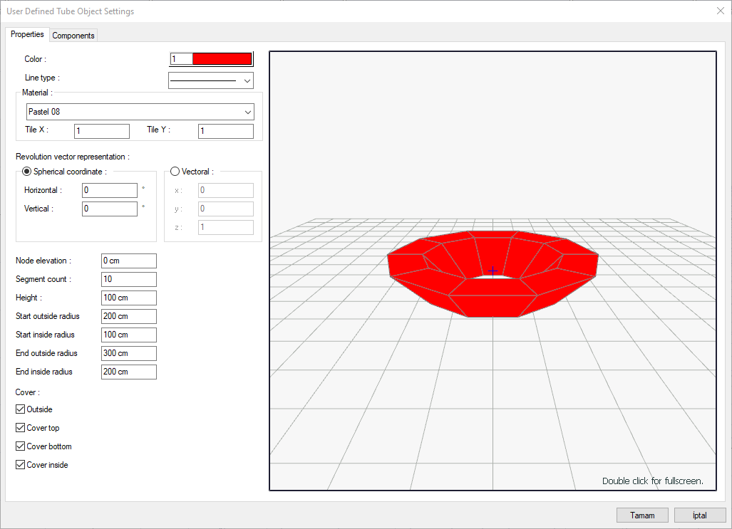
With the User Defined Tube Object Settings command, settings such as elevation, height, axis of rotation, radius, segment counts and material selection are accessed.
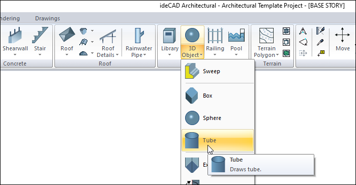
Location of User Defined Tube Object Settings Command
Click on the user defined tube object icon from the Tubes toolbar opened after entering the Tube command under the Entities title of the ribbon menu Home tab. After entering the user-defined tube object command, you can access it by clicking the Settings icon.
Properties Tab
|
Specifications |
|---|
|
Color Select the color of the tube object from the color palette that opens when clicked. |
|
Line type Select the line type of the tube object that appears in the plan from the drop-down list when clicked. |
|
Materiel Select the material of the object from the material list that opens when clicked. |
|
Tile X/Y Determines the number of times to repeat the texture to be wrapped around the object in the X and Y direction. |
|
Spherical coordinate/Horizontal It is the angle that the axle makes with the horizontal (x-axis). |
|
Spherical coordinate/Vertical It is the angle that the axis makes with the vertical (z-axis). |
|
Vectoral X/Y/Z 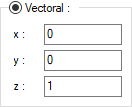
Coordinate values that express the vector direction of the rotation axis. |
|
Node elevation The object is elevated according to the floor base. |
|
Segment count It is the value that determines the number of surfaces of the object to be created. |
|
Height It is the height of the created object. |
|
Start outside radius The start radius of the outside surface of the tube object is entered. |
|
Start inside radius The start radius of the inside surface of the tube object is entered. |
|
End outside radius The end radius of the outside surface of the tube object is entered. |
|
End inside radius The end radius of the inside surface of the tube object is entered. |
|
Cover 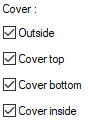
The surfaces to be left open or closed respectively are marked. If it is checked, the relevant surface is closed. |
|
3D preview 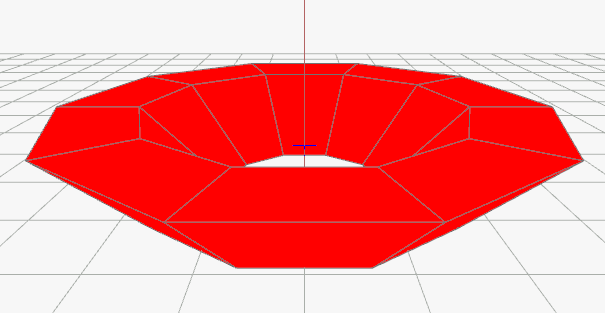
It is a 3D view of a user-defined tube object. You can rotate the image around itself by holding down the left mouse button and moving it. You can zoom in and out by holding the right mouse button and moving the mouse. |
Next Topic