
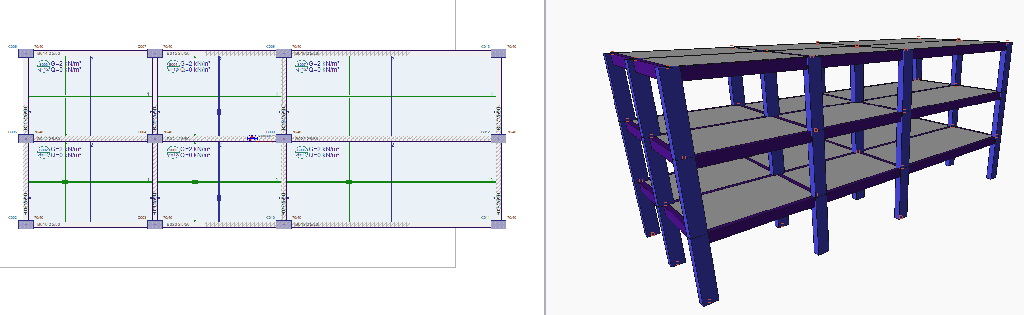
The reinforced concrete structure, which you can see in the above plan and 3d view, consists of 3 axis, 2 6 m and 10 m, in the X direction, while it has 2*4 m openings in the Y direction. The structure modeled as a reinforced concrete moment frame and semi-rigid diaphragm is solved by dynamic (modal) analysis in accordance with the dynamic accidental torsion method and earthquake effects will be determined by modal combining method. Below is a comparative model and outcome review with ETABS.
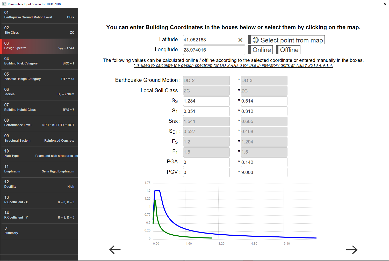
Soil parameters for latitude and longitude TBDY 2018 of the building, elastic spectrum values and Risk category, SDC etc. The classification is shown in the image below. C30 S420 material is used for frame elements and C20 S420 material is used for floor.
Project data: Solutions were made with ETABS v17 and ideCAD Statik v10.91.
3kat_13.11.2018-asıl sepktra-YARI.EDB0173_6_slab_3_story_yarı rijit.ide10
SOLUTION:
1- Analysis Results
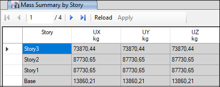
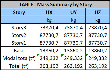
a) Structure Weight
-
Story based
ideCAD Structural
ETABS
-
Total
ideCAD Structural
ETABS
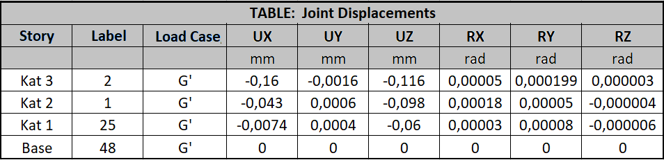
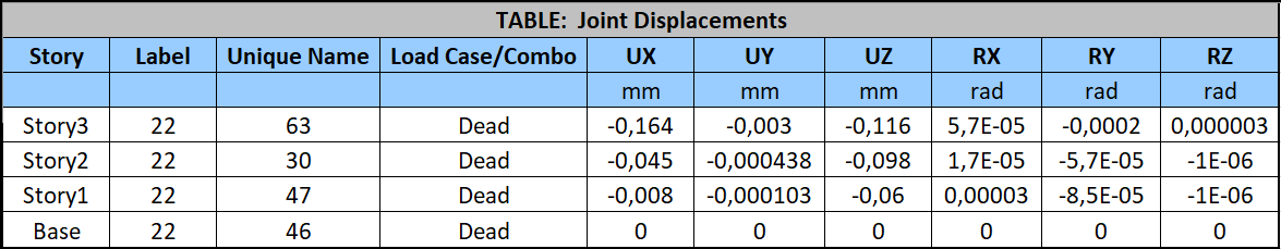
b) Vertical Results
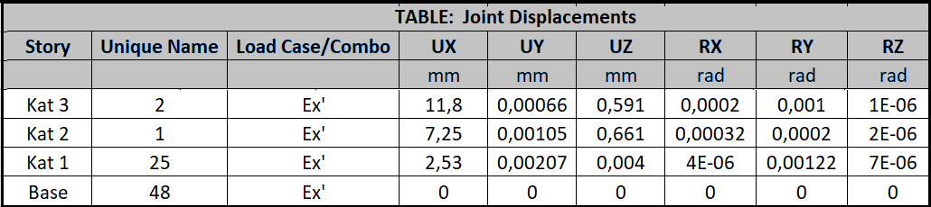
1- Displacement
In the ideCAD model, the joint values of N2 - N1 - N25 - N48 were read in order, starting from the upper floor located between column C0013 and beam B016 - B017.
ideCAD Structural
ETABS
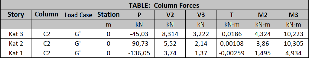
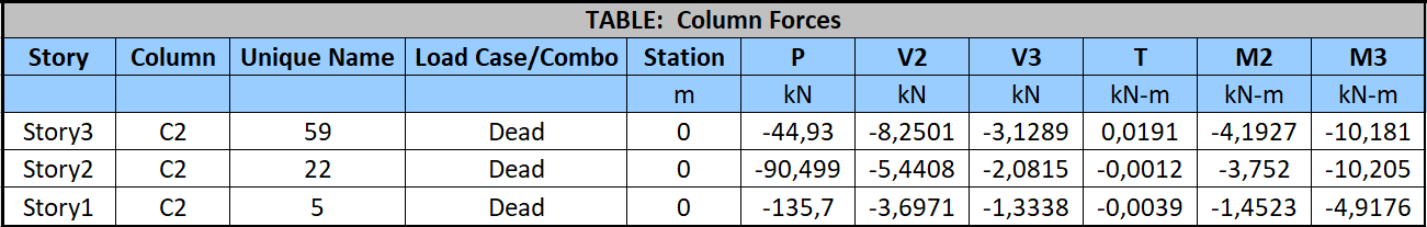
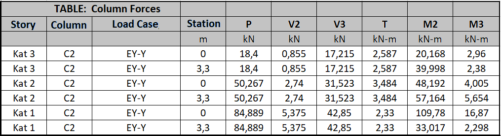
2- Frame Results
ideCAD Structural
C0002 corner column
ETABS
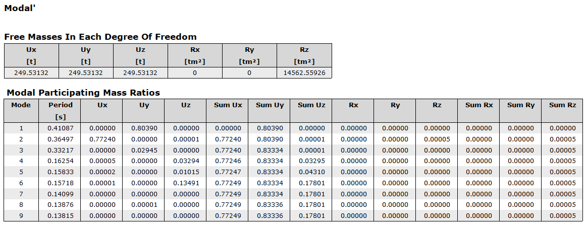
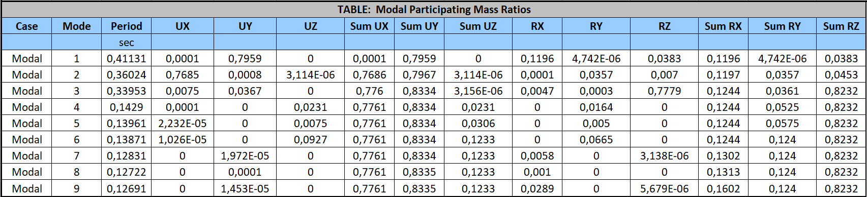
c) Modal Analysis
ideCAD Structural
ETABS
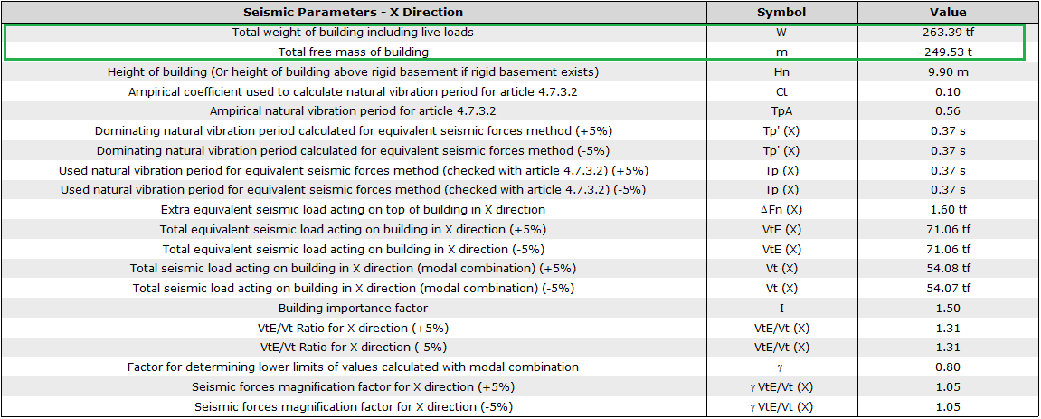
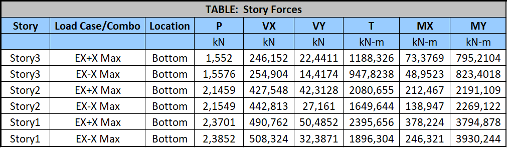
d) Seismic Force Results
1- Displacement
ideCAD Structural
ETABS

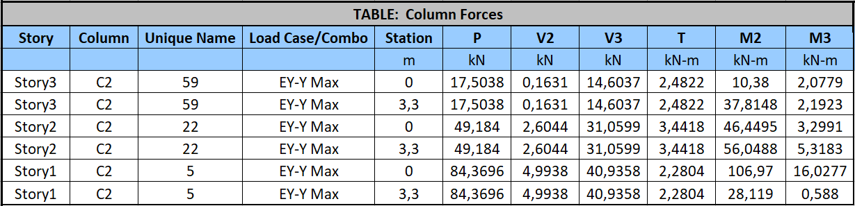
2- Frame Results
ideCAD Structural
ETABS
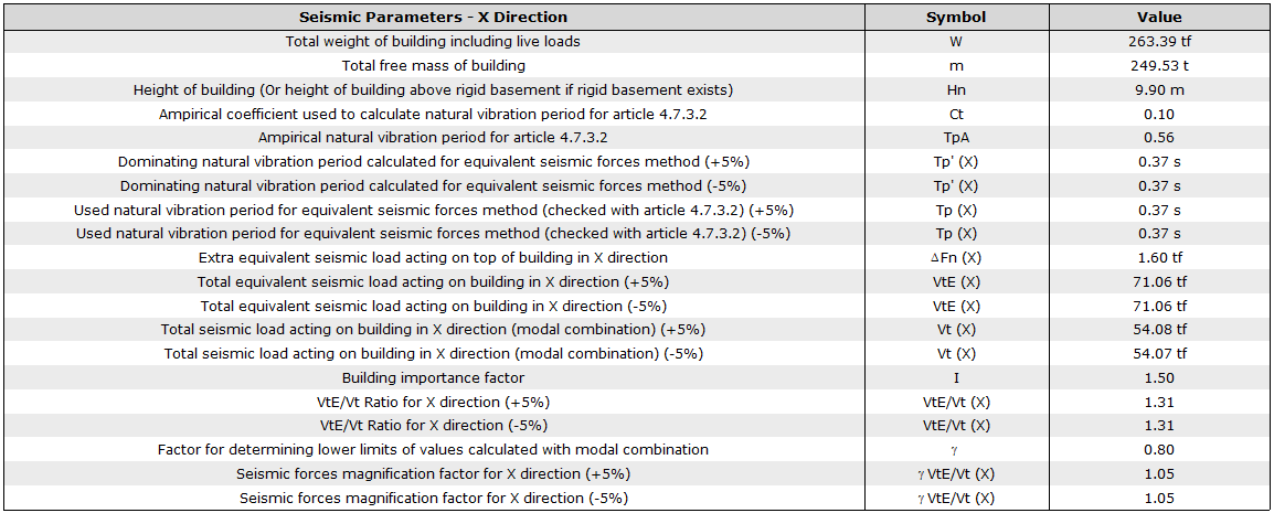
e) Calculation of the Amplification Factor according to the Equivalent Seismic Load Method
Equivalent Lateral Force Method Seismic Response Coefficient for Equivalent Lateral Force Method per ASCE 7-16 with ideCAD
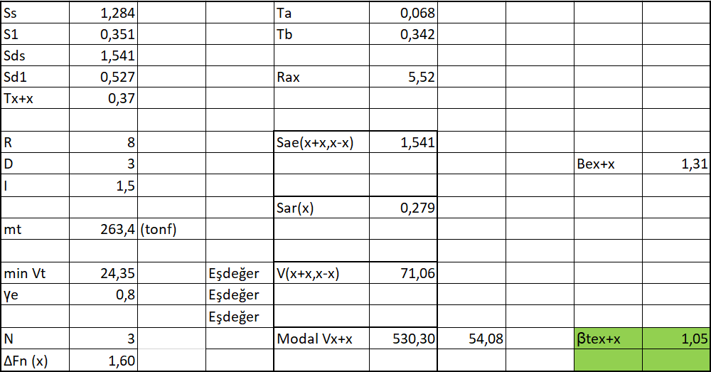
The information used in the calculation in the ideCAD Structural Dynamic analysis report is summarized below.
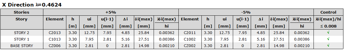
f) Relative Story Drift Calculation
Determination and Limitation of Story Drifts per ASCE 7-16 §12.12
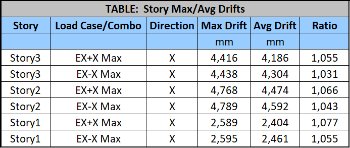
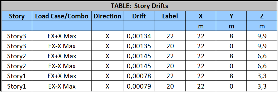
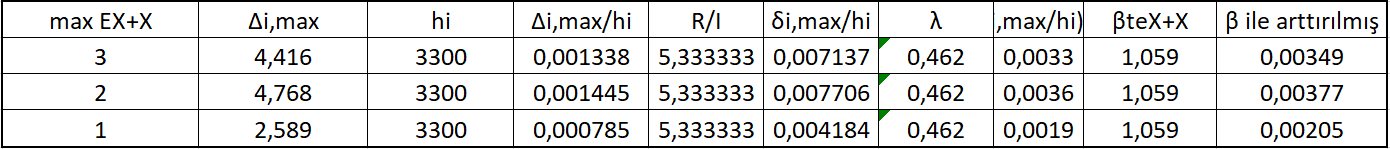
The calculation made in the relative story drift section of the ideCAD Structural Seismic regulation report is below.
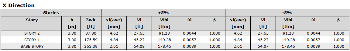
g) Second Order Effect Calculation
P-Delta Effects per ASCE 7-16 with ideCAD section is the philosophy of the account and how it is done. This account cannot be obtained directly from ETABS. The necessary data is taken from ETABS and calculations are made manually.
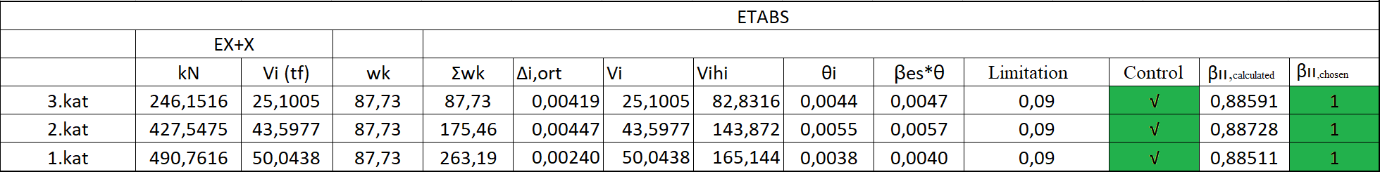
Calculation results are given in the second-order effects section of the ideCAD Static Earthquake regulation report.
Next Topic