
-
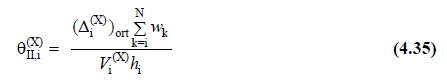
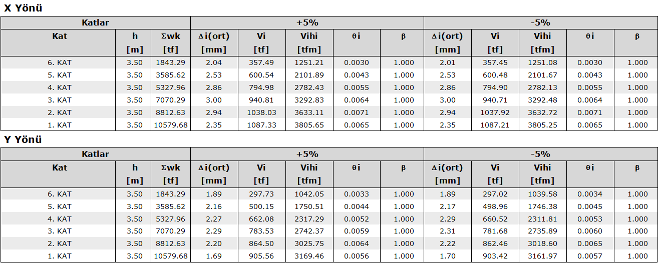
For both directions , the second order display value is automatically calculated with Equation 4.35 at each floor .
-
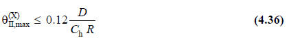
If the second order indicator value determined for all floors conforms to the limit value calculated by Equation 4.36 , the second order effects are not taken into account in the calculation of the internal forces based on the design.
-
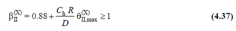
If the condition given in Equation 4.36 is not fulfilled, all internal forces are automatically increased by the second order magnification factor calculated by Equation 4.37 .
-
This control for both directions is done automatically only for the upper section in buildings with basement.
Symbols
|
θII,i(X) |
(X) second order indicator value defined for each i'th floor in the earthquake direction |
|
θII,max(X) |
(X) maximum second order indicator value defined in the direction of the earthquake |
|
V i (X) |
(X) reduced floor shear force at the i'th floor in the earthquake direction [kN] |
|
hi |
The height of the i'th floor [m] |
|
∆ i , ort (X) |
(X) mean reduced relative storey drift expressing the displacement difference between two consecutive floors in the earthquake direction [m] |
|
wk |
Total weight acting on the kth floor [kN] |
|
β II (X) |
Second order magnification factor |
The load-bearing system calculation, which is made as a standard under the influence of various loads, is essentially made over an unchanged (not deformed) system. However, taking into account the deformed shape, additional behavior magnitudes (internal forces and displacements, etc.) can be calculated in the carrier system. The effect of the deformed shape of the carrier system can be taken into account in two ways. In the former, the deformed shape is taken into account in both geometrical fitness conditions and equilibrium conditions. This approach, called the "Large Displacement Theory", can only be applied in flexible systems with very large deformation. In practice, the approach used especially for building bearing systems is the "Second Order Theory", which opposes the deformed shape to be considered only in equilibrium equations.
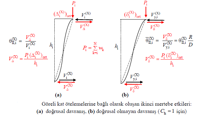
It is necessary to calculate the "second order effects" that occur as a result of horizontal loads (relative floor displacements) occurring in the vertical elements of the bearing system under the effect of earthquake ground motion in general, and should be taken into account in the design. Because these effects cause both "stiffness loss" and "strength loss" especially due to nonlinear behavior in the conveyor system. If both effects take too large values, it may ultimately lead to loss of stability (buckling) in the conveyor system and eventually collapse.
However, it is not an easy task to obtain second-order effects in earthquake calculation within the scope of Design Based on Strength, and it is contented with approximate methods. In the approximate methods considered in TBDY 2018 and which are very similar to each other, rigid diaphragm is accepted and torsional effects are neglected. The second order effect is taken into account depending on the increase coefficient calculated by Equation 4.37.
The C h parameter is used to indicate the difference in hysteretic behavior of reinforced concrete and steel structural systems under second order effect. The elasto-plastic cyclic hysteretic behavior valid for steel causes the second order effects to increase after flowing, while the hysteretic behavior, which is valid in reinforced concrete and includes online stiffness loss, limits the second order effects after flowing relatively.
Details of the calculations made in the Second Order section of the earthquake regulation report are given.
Related Topics