
Symbols
c = Distance of curtain parts between cross-section gravity centers
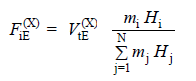
FiE = Total load actingon the floor
m = Mass of the relevant floor
H = The height of the upper section of the i'th storey measured from the base of the building [m]
M1 = Bending moment at the base of the curtain part due to the earthquake effect
M2 = Bending moment at the base of the curtain due to the earthquake effect
MDEV = Total overturning moment at the curtain base
Nv = Axial force at the curtain base
Ω = Degree of commitment
VtE = Total load selected to be distributed across building floors at inverted triangle unit loading
General Assesment
-
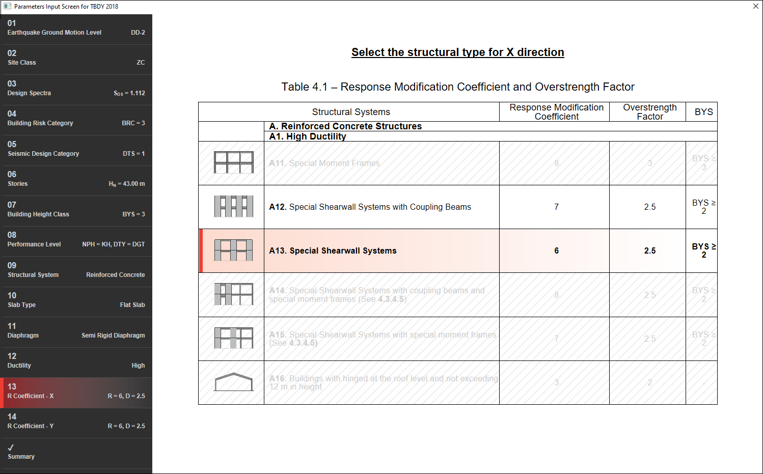
The structural system of the building is created with flat slab and shearwalls. As required by TBDY 2018 4.3.4.4, all of the earthquake impacts should be covered by special shearwalls and / or special shearwalls with coupling beams with limited ductility level in structural systems containing flat slabs. Due to the building's BYS = 3 and high ductility level, A12 or A13 bearing systems should be selected for the structural system type.
-
Special shearwalls in the X-X direction of the building and special shearwalls are used together. In order to be able to make the appropriate R and D selection for the hollow screen, we first need to check the degree of special shearwall with coupling beams. According to TBDY 2018 4.5.4.5 condition, this check is performed automatically.
-
However, in order to stay on the safe side, since R coefficient of special shearwalls with coupling beams is lower, special shearwall is chosen for the X direction.
-
On the Y direction of the building, all of the earthquake effects are covered by special shearwalls.
Degree of Coupling and Special Shearwall with Coupling Beams Acceptance
-
The degree of adherence of U-shaped shearwall formed by connecting two U shearwall arms at the core of the building with coupling beams should be checked in accordance with TBDY 2018 4.5.4.5. If the degree of commitment is equal to or greater than 1/3, we can consider this shearwall group as a compound shearwall.
-
The important issue in this calculation is the stiffness distribution within the wall group. Therefore, for ease of calculation, the core shearwall is separated from the building and analyzed separately.
-
In this calculation, an inverted triangle unit is loaded from the top floor to the lowest floor. For the load distribution, the equations used in the distribution of equivalent earthquake load according to floors are used. The only difference is that there is no additional force on the top floor. The point to note here is that this loading is not applied to the basement floors, this process is applied between the first floor above the basement floor and the last floor.
Note: VtE in this equation is the total load we selected in this calculation. The numerical value of the load does not matter.
-
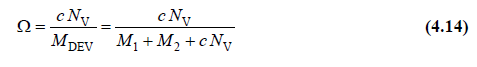
The equation used for calculation is:
-
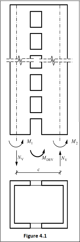
Here, the total overturning moment at the base of the shearwall with coupling beam MDEV, M1 and M2 as the sum of the bending moments obtained at the base due to the earthquake effect in the shearwall parts forming the wall with coupling beams, and NV as the sum of the shear forces formed in the coupling beams under the earthquake effect along the whole wall height. Corresponds to equal tensile and compression axial forces formed at the base of the shearwall parts. c shows the distance between the cross-section gravity centers of the shearwall pieces.
-
In the program, this calculation is made automatically when the gap is selected and the results are detailed in the earthquake regulation report.

-
According to this control, our core shearwall is considered as a compound shearwall. However, as stated before, in order to stay in the safe zone, due to the fact that the shearwall with and without coupling beams work together in the X direction, an arrangement suitable for the shearwall without coupling beams is made in the selection of R and D.
Selected R and D Coefficients
-
A13 special shearwall selection is made for both directions.
Next Topic