
In the evaluation of linear performance analysis of existing structures , element ductility control is made according to shear safety of column-beam junction areas .
-
In the evaluation of the existing building, the element ductility control is made automatically by using the shear safety control of the column-beam joints .
ICONS
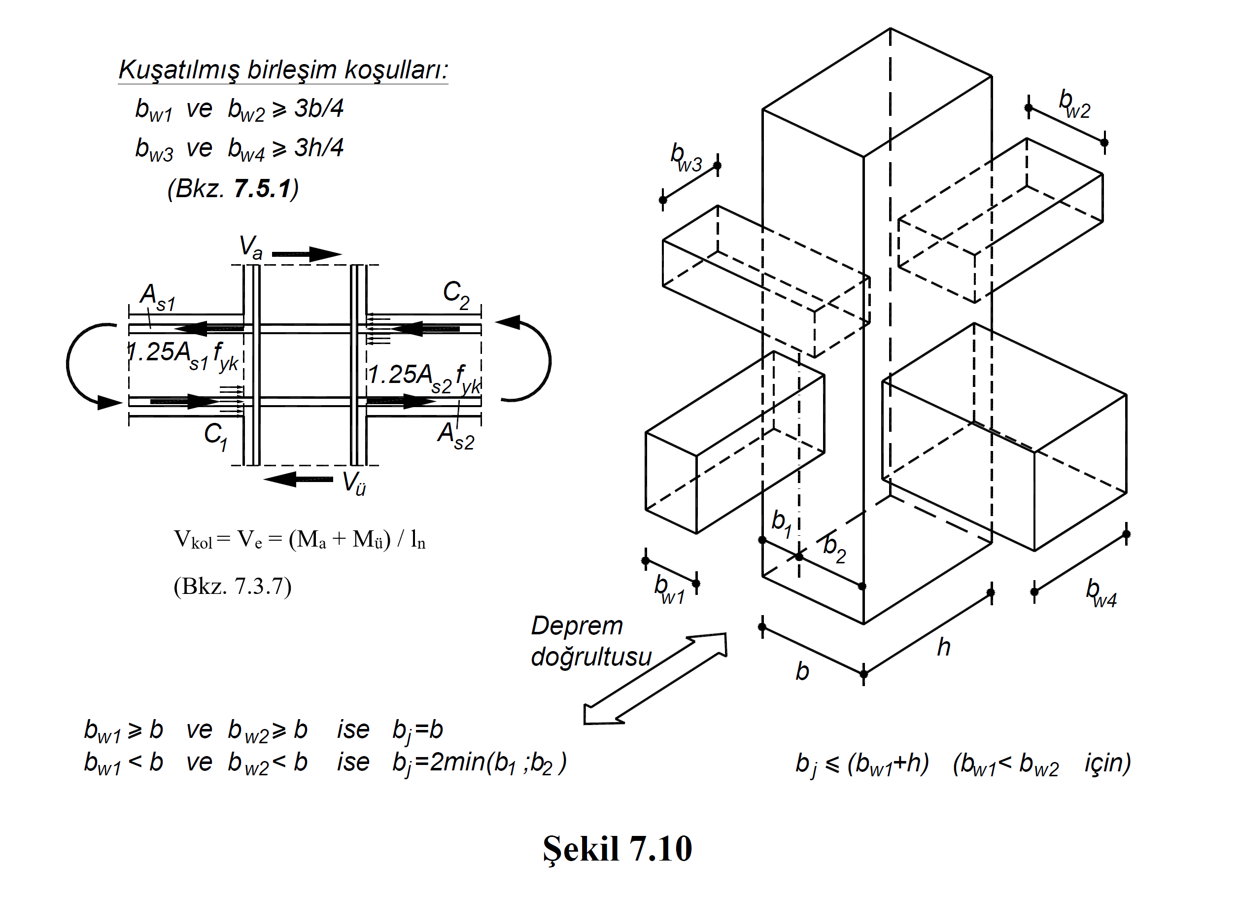
A s1 = Total area of the tensile reinforcement placed on one side of the column-beam node to accommodate the negative moment of the beam
A s2 = Thetotal area of the tensile reinforcement placedon the other side of the column-beam node with respect to As1 to accommodate the positive moment of the beam
b j = In the earthquake direction considered, if the beam stuck in the joint area is the same width as the column or protrudes from both sides of the column, the column width, otherwise, twice the distance from the vertical middle axis of the beam to the column edges
f ck = Concrete characteristic cylinder pressure strength
f yk = Characteristic yield strength of reinforcement steel
h = Cross-section dimension of thecolumn in thedirection of the earthquake
l n = The free height of the column between the beams, the free span of the beam between the column or curtain faces
M a = At the lower end of the column's rigid height, the basis of the column shear force calculation is the moment value received.
M ü = It is the moment value which is taken as basis in calculation of column shear force at the upper end of the free height of column.
V e =Design shear force calculated at column-beam junction
V arm = above and below the node point, the smaller of the column shear forces calculated according to Section 4
In evaluating the performance of existing structures under the effect of earthquake, while earthquake calculation is applied with linear calculation methods , element ductility control is made according to shear safety of column-beam joints .
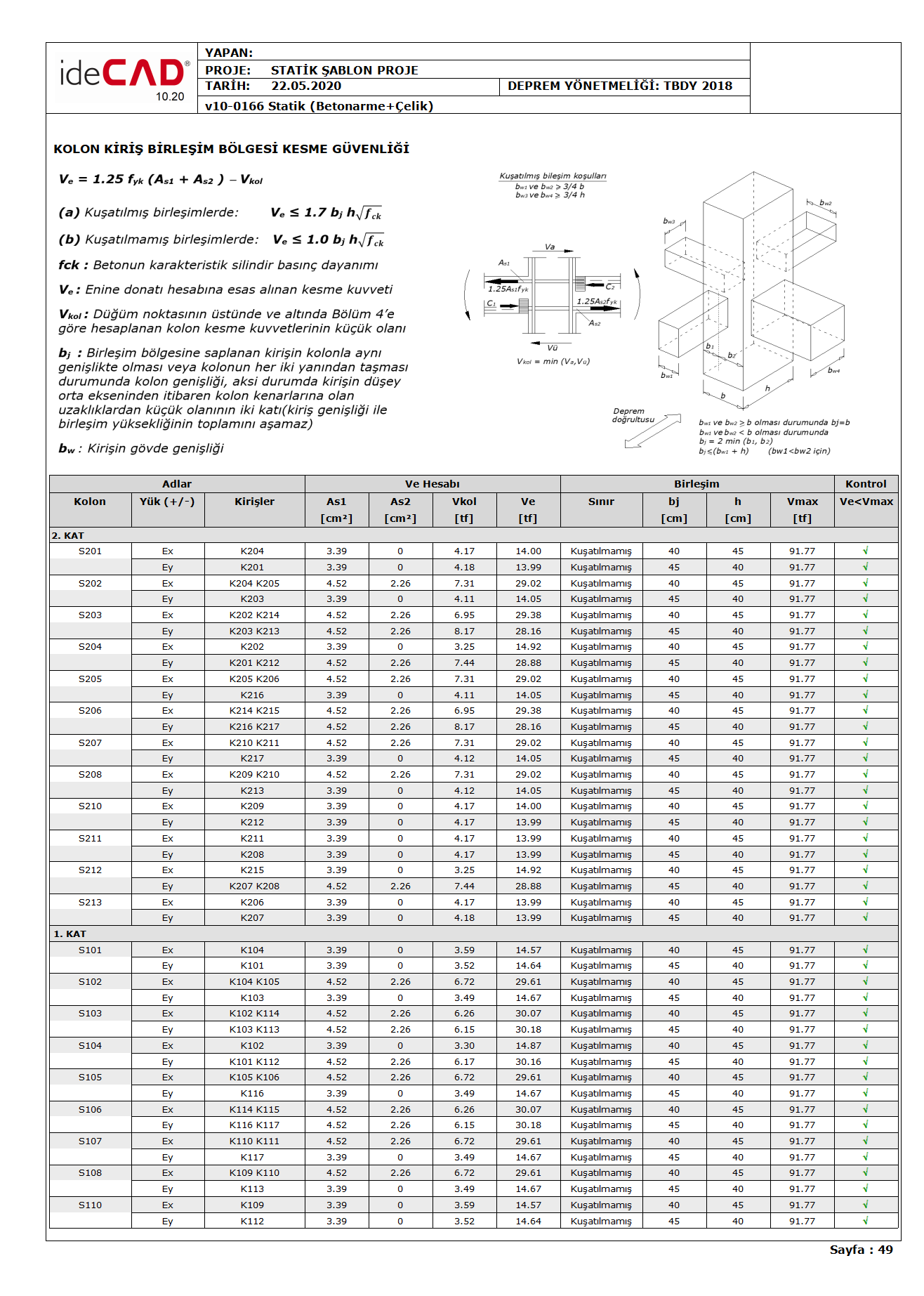
The forces affecting the connection for all boundary situations in reinforced concrete column-beam joints are calculated from Equation (7.11) given in Section 7.5.2 of TBDY .

In this equation, V e is the design shear force calculated at the column-beam junction. A s1 is the total area of the tensile reinforcement placed on one side of the column-beam node to accommodate the negative moment of the beam, A s2 is the total area of the tensile reinforcement placed on the other side of the column-beam node relative to A s1 to meet the positive moment of the beam. In the above equation, f yk reinforcement expresses the characteristic yield strength. However, in the performance analysis of existing structures, when ductility control of the column-beam junction area is performed, the existing material strength is used by considering the information level coefficient instead of the f yk value .
Existing structures while ductility control element performance analysis Eq. (7.11) from V handle value TBDY Section 7.3.7 as indicated in Eq. (7.5) is calculated by (V rod = V e (denk.7.5) ). This value is the shear force value calculated with the current material strength, taking into account the information level coefficient calculated under the shear safety condition of the columns . M a and M ü are the moment value which is taken as basis in calculation of column shear force at the lower and upper end of the free height of column , respectively. V e , M a and M ü for columnsColumn Shear Design Forces

The value of V e calculated from Equation (7.11) as the basis for the column-beam joint shear safety calculation should not exceed the shear strength given in Equation (7.12) and Equation (7.13) given in TBDY 7.5.2.2 .


In the above equation, f ck expresses the characteristic compressive strength of concrete. However, in the performance analysis of existing structures, when ductility control of the column-beam junction area is performed, the existing material strength is used by considering the knowledge level coefficient instead of the f ck value .
If the V e value calculated from Equation (7.11) does not meet the boundary conditions specified in Equation (7.12) and Equation (7.13) , the column-beam joint area is defined as a brittle damaged element . If the conditions are met, it is classified as a ductile element.
Next Topic