
-
For walls meeting the H w / l w > 2.0 condition, the bending moments based on the design are taken as a constant value along the critical wall height determined according to 7.6.2.2 , equal to the bending moment calculated at the base of the wall according to Section 4 , the condition is automatically controlled.
-
Above the section where the critical wall height ends , the linear moment diagram parallel to the line combining the moments calculated at the base and top of the wall according to Section 4 is automatically applied.
-
In buildings with basements that meet the conditions given in 3.3.1.1 , the constant curtain moment is taken into account along the critical wall height defined in 7.6.2.2 .
-
The condition that design bending moments in all sections of walls with H w / l w ≤ 2.0 are equal to the bending moments calculated according to Section 4 is automatically applied.
-
In the case of H w / l w > 2.0, it is automatically checked whether the moment of bearing power of the wall sections at each floor is fulfilled for the columns in the strong direction of the wall , given by Equation (7.3) .
ICONS
H w = Total curtain height measured from the top of the foundation or the ground floor slab
H cr = Critical curtain height
l w = Length of the curtain or tie-beam curtain piece in plan
Polygon Curtain Design Bending Moments under H w / l w > 2 and H w / l w <= 2
Curtain elements are modeled with shell finite elements. In this case, all the stresses of the curtain element, both in-plane and out-of-plane, are calculated for each loading combination. The results of the curtain finite elements are defined at the center of gravity of the curtain section so as to provide the three-dimensional rigid body motion condition, and the internal forces of the curtain are obtained by summing the values obtained from the curtain finite element results of the respective loading combination at this center of gravity.
First , minimum longitudinal reinforcement and transverse reinforcement of wall elements are determined in accordance with Section 7.6 of TBDY . The element strengths obtained with these reinforcements are compared with the design forces obtained from the calculation. If the strength values are smaller than the design forces, the required element strength is obtained by revising the stipulated reinforcements.
All combinations of loading create a bending moment around both axes with the axial load on the curtain. In this case, a bending strength is calculated for each normal force level in the two axes (strong and weak axis) of the wall. When all these strengths are transferred to a graph in the form of PM2M3, the 3-dimensional interaction curve of the curtain is obtained. Since the bending strength of walls will be different normal strength levels for each loading combination, the biaxial bending strength of this wall is calculated by moment-curvature analysis.
The design bending moments of the walls in TBDY Clause 7.6.6.1 TBDY Figure 7.12 (a) and TBDY A constant value along the critical wall height, H cr , shown in Figure 7.12 (b) , at the base of the wall if above the section where the critical wall height ends, and are the values of the moment diagram parallel to the line joining the moments calculated at the top.
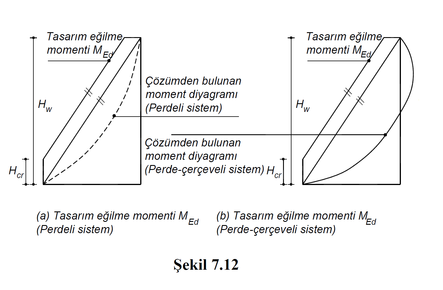
TBDY Article 7.6.6.1 according H w / l w > 2 curtaining satisfying design bending moments, TBDY Article 7.6.2.2 according to the wall base as a constant value over a defined critical wall height Chapter 4 'equal to the bending moment calculated according to the are taken. In this case, the base moment of the wall is the bending moment value calculated under the combined effect of vertical loads and earthquake loads. This bending moment continues steadily along the critical pitch height, H cr .
TBDY Figure 7.12 (a) and TBDY Figure 7.12 (b) "Moment diagram from the solution" represents the moment diagram for both systems (pitched, curtain-frame) under the joint effect of gravity loads and earthquake loads. The graph indicated by "design bending moment M Ed " is the moment diagram with the same value as the moment at the base of the wall along the critical curtain height, H cr . The critical pitch height, H cr , is the moment diagram at the top of the value, parallel to the line combining the base moment of the curtain with the ceiling moment.
Since the Design Bending Moment graph of the walls depends on the base moment, it is made separately for all combinations. In other words, the design bending moment value is calculated separately for all combinations in walls. Next, a 3-dimensional interaction curve (onion curve) is drawn, where a bending strength is calculated for each normal force level. After these values, the design rates of the curtain are found for each combination.
Next Topic