
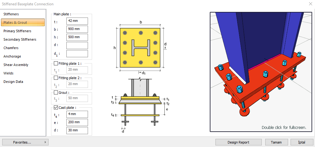
Column-Foundation Connection or Stiffened Base Plate Connection is formed by connecting the base plate welded to the steel column and anchored to the concrete foundation (column). Stiffened base plate design is made automatically according to the Design, Calculation and Construction Principles of Steel Structures (ÇYTHYEDY) (GKT and YDKT) and AISC 360-16 (ASD and LRFD) regulations. In the stiffened base plate connection calculation, bolt, weld and plate controls, geometry controls and strength controls are made automatically in accordance with the steel connection type.
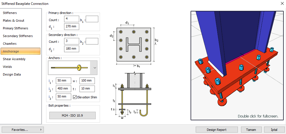
In the calculation of the stiffened base plate connection, the horizontal and vertical bolt distances and the distance between the bolts are controlled under the geometry control. In the strength control, base plate thickness, anchor pulling breakage, anchor rod peeling, anchor rod shearing, plate bolt hole controls are made.
Geometry Checks
Bolt Spacing
|
s min ≥ 3d |
ÇYTHYEDY 13.3.6 |
|
|
|
s |
180 mm |
|
|
|
d |
24 mm |
s =180 mm > smin = 3*24=72 mm |
√ |
Horizontal Edge Distance
|
L eh ≥ L e- min |
ÇYTHYEDY 13.3.7 |
|
|
|
L eh |
70 mm |
L eh ≥ 2d = 2 * 24 = 48 mm conformity check for application |
√ |
|
L e- min |
32 mm |
Minimum distance check according to Table 13.9 |
√ |
Vertical Edge Distance
|
L ev ≥ L e- min |
ÇYTHYEDY 13.3.7 |
|
|
|
L ev |
45 mm |
|
|
|
L e- min |
32 mm |
Minimum distance check according to Table 13.9 |
√ |
Strength Checks
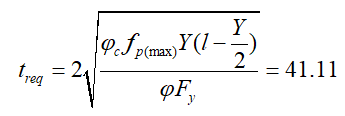
Base Plate Thickness (Bearing)
|
fc |
25000 kN/m2 |
|
|
A 1 |
|
|
|
A 2 |
|
|
|
qmax |
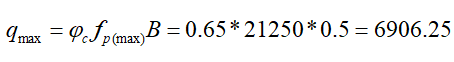
|
|
|
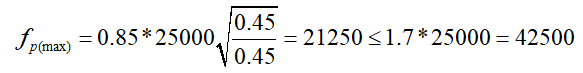
fp(max) |
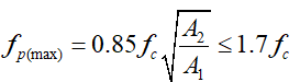
|
|
|
fp(max) |
|
|
|
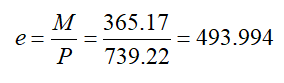
e |
|
|
|
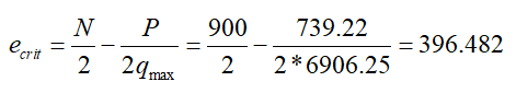
e crit |
|
|
|
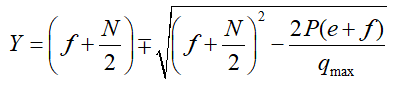
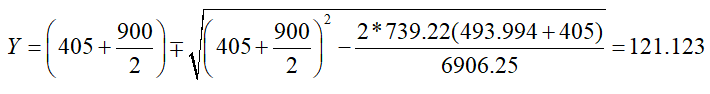
Y |
|
|
|
Y |
|
|
|
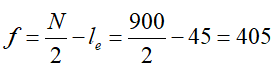
f |
|
|
|
le |
45 mm |
|
|
l |
|
|
|
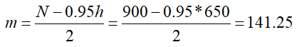
m |
|
|
|
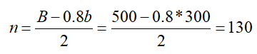
n |
|
|
|
h |
650 mm |
|
|
b |
300 mm |
|
|
N |
900 mm |
|
|
B |
500 mm |
|
|
M |
365.17 kNm |
|
|
P |
739.22 kN |
|
|
F y |
355 N/mm2 |
|
|
t req |
|
AISC DG-1-2 nd 3.3.15.a |
|
Required |
Available |
Ratio |
Control |
|---|---|---|---|
|
41.11 mm |
42 mm |
0.979 |
√ |
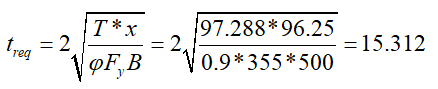
Base Plate Thickness (Tension)
|
fc |
25000 kN/m2 |
|
|
A 1 |
|
|
|
A 2 |
|
|
|
qmax |
|
|
|
e |
|
|
|
e crit |
|
|
|
T |
|
|
|
Y |
|
|
|
Y |
|
|
|
f |
|
|
|
x |
|
|
|
le |
45 mm |
|
|
m |
|
|
|
h |
650 mm |
|
|
N |
900 mm |
|
|
B |
500 mm |
|
|
M |
365.17 kNm |
|
|
P |
739.22 kN |
|
|
F y |
355 N/mm2 |
|
|
t req |
|
AISC DG-1-2 nd 3.4.7a |
|
Required |
Available |
Ratio |
Control |
|---|---|---|---|
|
15.312 mm |
42 mm |
0.365 |
√ |
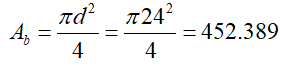
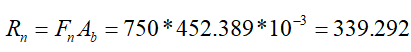
Anchor Rod Tensile Rupture
|
A b |
|
|
Fn |
750000 kN/m2 |
|
Rn |
|
|
ΦRn |
|
|
Required |
Available |
Ratio |
Control |
|---|---|---|---|
|
32.429 kN |
254,469 kN |
0.127 |
√ |
Anchor Rod Concrete Pullout
|
Ψ |
1.0 |
ACI 318M-08 D.5.3.6 |
|
N p |
|
ACI 318M-08 (D-15) |
|
A bgr |
7401.592 mm2 |
|
|
fc |
25000 kN/m2 |
|
|
Rn |
|
ACI 318M-08 (D-14) |
|
ΦRn |
|
|
|
Required |
Available |
Ratio |
Control |
|---|---|---|---|
|
32.429 kN |
1036.222 kN |
0.031 |
√ |
Anchor Rod Shear
|
A b |
|
|
Fn |
|
|
Rn |
|
|
ΦRn |
|
|
Required |
Available |
Ratio |
Control |
|---|---|---|---|
|
9.995 kN |
152,681 kN |
0.065 |
√ |
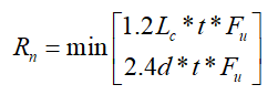
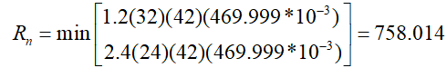
Bolt Bearing on Plate
|
d h |
24+2=26 mm |
|
|
Lc,edge |
|
|
|
Rn |
|
ÇYTHYEDY 13.3.13 Equation 13.14a and13.14b |
|
Rn-edge |
|
|
|
Rn |
|
|
|
ΦRn |
|
|
|
Required |
Available |
Ratio |
Control |
|---|---|---|---|
|
9.995 kN |
568,511 kN |
0.018 |
√ |