
-
According to TS 500, the minimum bending and shear reinforcement of the foundation will be determined first. The element strengths obtained with these reinforcements will be compared with the design forces obtained from the calculation. If the strength values are smaller than the design forces, the required element strength will be obtained by revising the foreseen reinforcements.
-
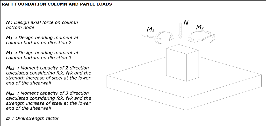
Determination of Internal Forces Acting on Foundations (4.10.3)
-
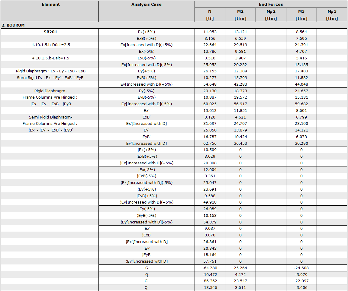
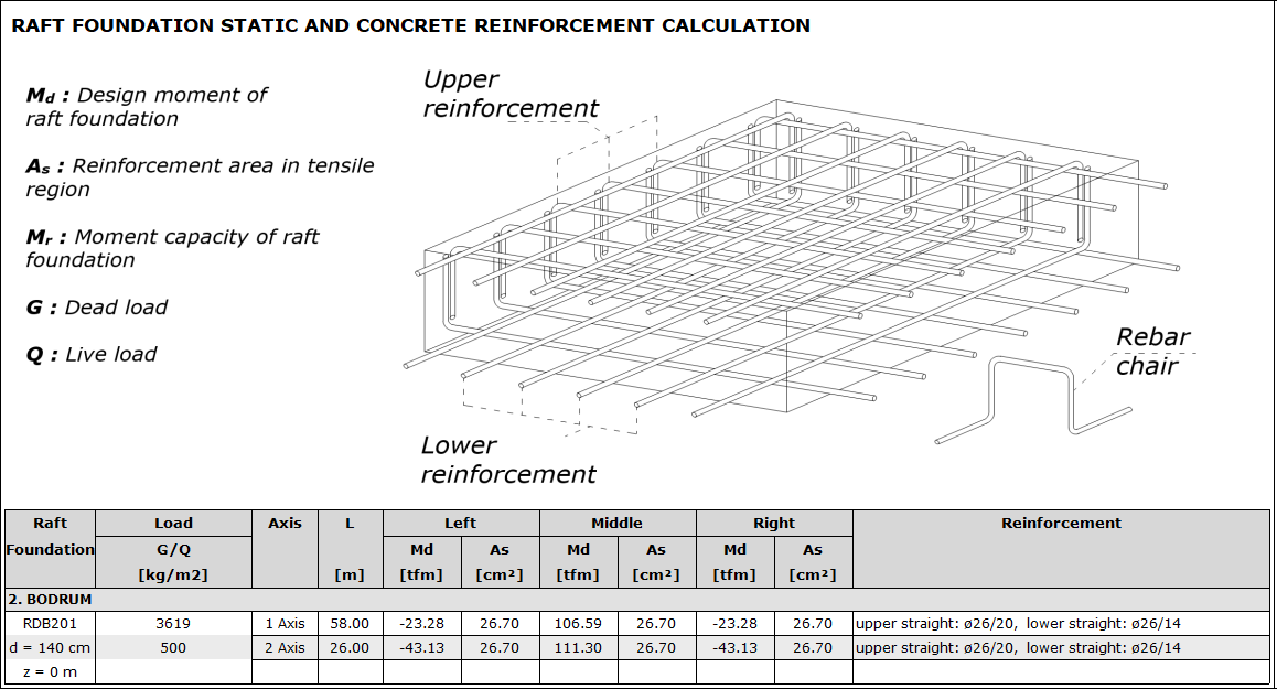
The raft foundation was used in the building and the upper structure interactive solution was applied. In the raft foundation report, loads from the upper section to the foundation and their calculations are reported as follows.
-
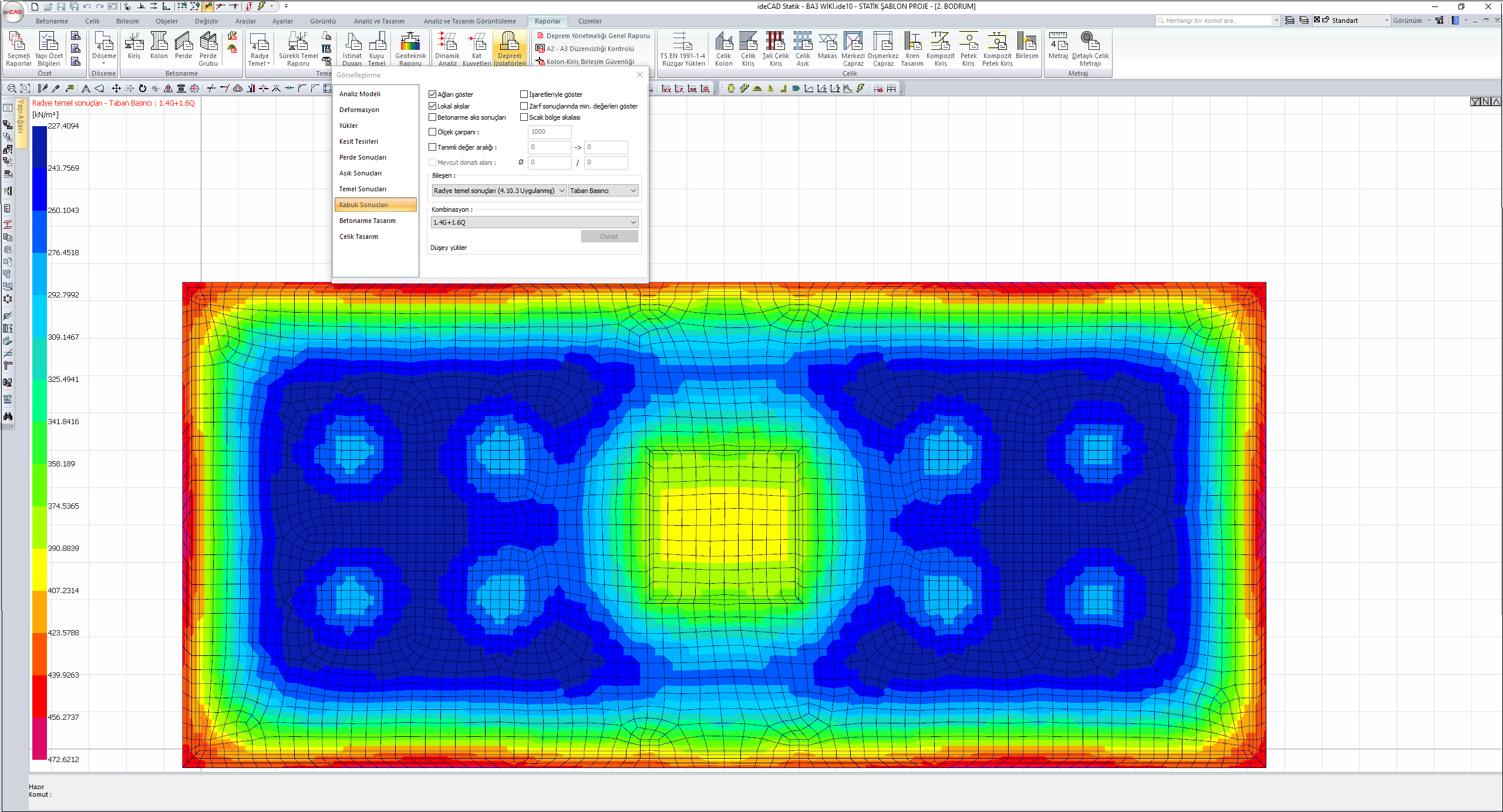
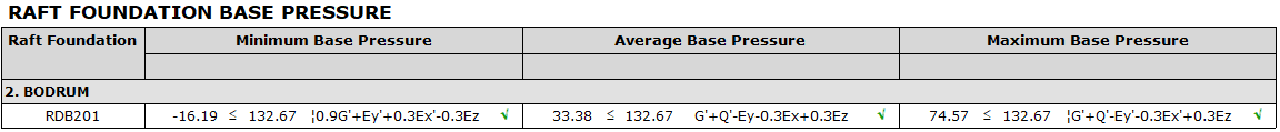
The stresses belonging to the load combinations resulting in maximum ground stress in both directions with increased vertical loads are as follows. The soil stresses shown below are less than the foundation bearing strength design stress qt = 1301 kN/m2.
-
In the geotechnical report, the base pressure control is summarized as follows.
-
The reinforcement calculation is given in the raft foundation report in detail.
-
Since the foundation is a slab element that works in two directions, the sum of the reinforcement ratios in both directions cannot be less than 0.0035 for B420C, provided that it is not less than 0.0015 in each direction, as required by TS 500 11.4.5. The range of reinforcement cannot be more than 200 mm.
Foundation thickness: 140 cm, material: C35 B420C
As,min=0.00175*140*100=24.5 cm2
Projected minimum reinforcement Φ26/20 = 26.55 cm2
-
This reinforcement is the minimum reinforcement that should be all around the foundation slab. The minimum design moment Md, min corresponding to this reinforcement is calculated as follows:
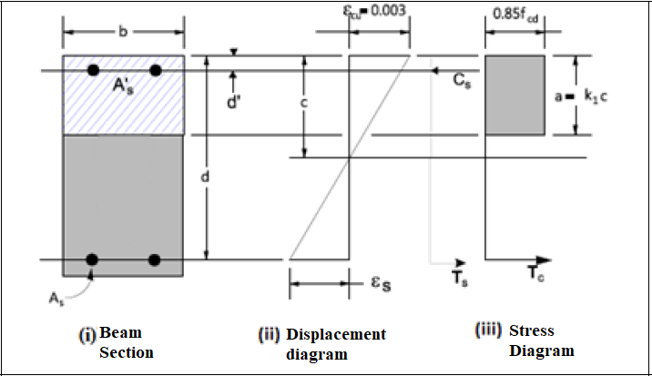
k1 = 0.85-0.006 (f ck -25) 0.70≤ k 1 ≤0.85
K1 = 0.79 for concrete class C35
a=k1*c=0.79c
Cs=Ts
0.85 * f cd * b * a = A s * f yd
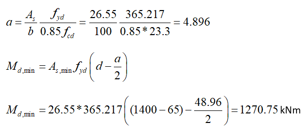
-
When the design moment values of the foundation slab in XX and YY direction are compared with the minimum moment value obtained for the minimum reinforcement above, it is seen that the minimum reinforcement area is not sufficient and additional reinforcement is required in some regions. For YY, in the region in the red box in the image below, M d = 1940 kNm / m has been determined. The additional foundation equipment required for this region is calculated below.
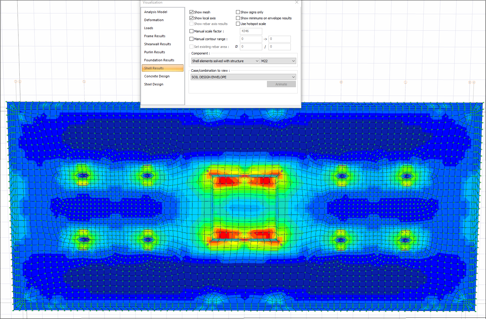
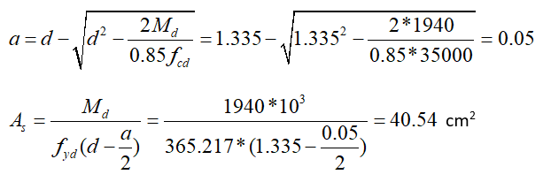
Existing reinforcement Φ26/20 = 26.55 cm2
Additional reinforcement Φ20/20 = 15.71 cm2
Total reinforcement Φ26/20+Φ20/20 = 42.26 cm2
-
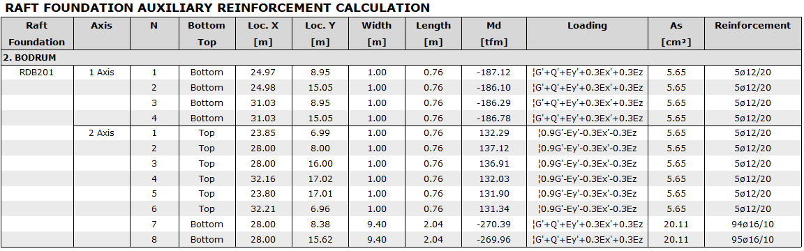
Additional reinforcements settled in the raft foundation report are also reported.
Next Topic