
Section Elevation command used to show elevations, story level etc. in sections and views. This command is only used in 2-dimensional drawing windows like section, view, etc. It is not active in 3D drawing windows.
Section elevations are also smart dimensions. If the dimension is moved, its displayed value changes. If it is wanted to unchange, the elevations explode into pieces with explode command. The value can be changed with the Edit Text command.
Location of the Section Elevation Command
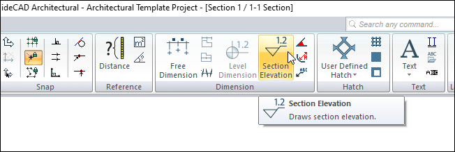
In the Architectural Program
You can access it under the ribbon menu Drawings tab, Dimension heading.
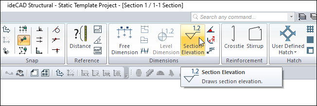
In Structural Program
You can access it under the ribbon menu Drawings tab, Dimension heading.
Dimension Toolbar
|
Icons |
|---|
|
Outer dimension Outer dimension command runs. |
|
Inner dimension Inner dimension command runs. |
|
Free dimension Free dimension command runs. |
|
Intersection dimension Intersection dimension command runs. |
|
Label Runs the label command. The dimension label is drawn. |
|
Level dimension Draws level dimension in the plan window. |
|
Section elevation It is used for section elevation in section and view windows. Only active in 2D drawing windows. |
|
Angle dimension Dimensions the angle between two objects. |
|
Radius dimension Dimensions entities drawn with a circle or arc and arc or circle axis in diameter or radius. |
|
Section dimension group Creates a section dimension group. It is active in section and view windows. |
|
Section dimension Creates a section dimension. It is active in section and view windows. |
|
Include beams Include beams in dimension. |
|
Include slabs Include slabs in section dimension. |
|
Include details Include door/window elements in section dimension. |
|
Left side Places the section dimension on the left. |
|
Right side Places the section dimension on the right. |
|
Settings When clicked, which dimension type is active (inner, outer, intersection etc.) opens the dimension settings dialog where the parameters related to that dimension are found. |
Usage Steps
To create a section elevation:
-
Click the Section Elevation icon in the ribbon menu .
-
Click the point on the section or view you want to elevate with the left mouse button. The elevation icon will appear at the clicked point.
-
You can slide the label to the right by pressing the space key on the keyboard.
-
If you want to swipe the label to the left, first press the S key. Then press the space key. The label will shift to the left.
-
When the elevation label is in the position you want, click the left mouse button. The process will be completed.
|
Usage step |
|---|
|
Determining the point to be elevated from the section or view page 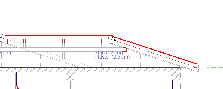
|
|
Clicking the left mouse button to create the elevation icon 
|
|
Scrolling the label by pressing the spacebar 
|
|
Creating the section elevation by clicking the left mouse button 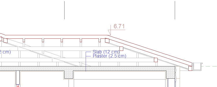
|
Location of Section Elevation Settings Dialog
Section Elevation Command Settings
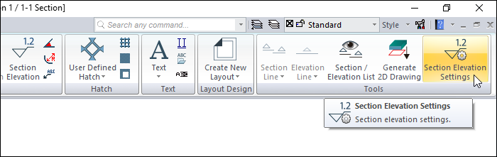
After running the section elevation command, you can access it by clicking the Settings icon in the dimension assistant toolbar that appears on the screen.
You can also access it from the Drawings tab, under the Tools heading in the architectural program .
Section Elevation Object Settings
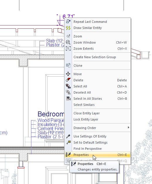
Select the section elevation that you want to enter its settings and click the Properties row from the menu that opens by clicking the right button of the mouse.
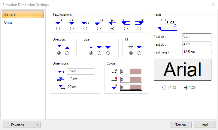
Elevation Settings - General Tab
|
Specifications |
|---|
|
Text location 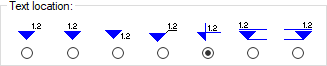
The position of the elevation text relative to the icon is selected. |
|
Direction 
The direction of the elevation arrow is selected. |
|
Size 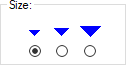
The size of the elevation arrow is selected. |
|
Fill 
Display type of elevation arrow is selected. |
|
Text section |
|
Text dx/font dy 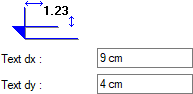
By entering the values entered in the Text dx, Text dx and Text dy boxes, the location of the text is adjusted according to the elevation symbol. |
|
Text height The height of the elevation text is entered. |
|
When the button is clicked, the "Font Settings" dialog appears. Font of information text can be set here. |
|
One of the 2 display types given for elevation text is selected. |
|
Dimensions Section |
|
The height of the elevation arrow is entered. |
|
Line length on the left side of the elevation icon is entered. |
|
The length of the line on the right side of the elevation icon is entered. |
|
Colors section |
|
Adjusts the color of elevation text. When the color box is clicked, the appropriate color is selected from the window that opens. |
|
Adjusts the color of the elevation lines. When the color box is clicked, the appropriate color is selected from the window that opens. |
|
Sets the color of the elevation arrow. When the color box is clicked, the appropriate color is selected from the window that opens. |
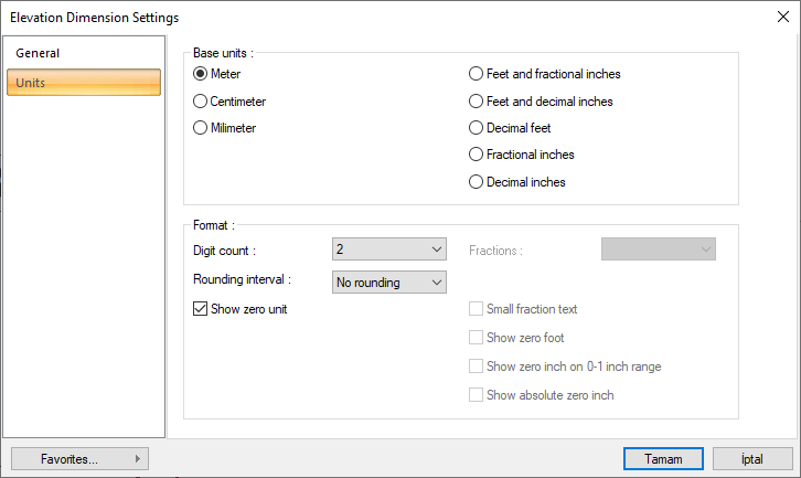
Elevation Dimension Settings - Units Tab
|
Specifications |
|---|
|
Basic units 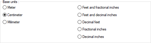
One of the selections is activated by clicking the left mouse button on the job. Meter : If checked, the unit of information text will be meters.
|
|
Digit count 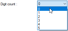
It determines how many digits will be shown after the comma. The desired number is selected from the list. For example, if 2 is selected, units will be shown as two digits after the comma. If 0 is selected, units will not be shown after the comma. |
|
Fractions 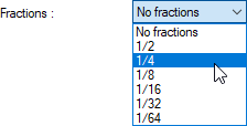
It determines the precision of the dimension to be made in fractional inch format. In the list, there are options with a sensitivity of 1/2, ¼, 1/8, 1/16, 1/32, 1/34. If "no fraction" is selected, units will appear without fractions. |
|
Rounding interval 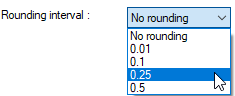
It determines the rounding range of the measurement to be made in meters, centimeters or millimeters. If No rounding is selected, the dimensioning is done at exact value. As the range gets larger, the dimensioning is rounded up to the selected range. |
|
Show zero unit If it is not checked, it does not show the zero and point on the left in dimensioning. For example, it measures 0.20 as 20. If marked, the value 0.20 is scaled as 0.20. |
|
Small fraction text When fractional inch format is selected, determines the fractional part to display in upper / lower case. If it is checked, the fraction is slightly above the integer and small, if not, the fraction is shown the same size next to the integer. |
|
Show zero foot Determines whether 0 is displayed in the 0-foot gauge (less than 1 foot gauge). For example, if it is not checked, it will show a measure of 0 '- 15 "as -15". If marked, it shows as 0'-15 ". |
|
Show zero inch on 0-1 inch range For example, a dimension inch with a value of 8'-0 1/6 "is in the range 0-1. If the option is not ticked, the value 8'-0 1/6" will be displayed as 8'-. In other words, inch values in the 0-1 range will not be displayed. |
|
Show absolute zero inch Determines whether to show zero inches in the dimension value where inches is absolute zero. For example, a dimension of exactly 10 'will be displayed as 10'-0 "if this option is selected. If not checked, it will be displayed as 10" -. |
Next Topic