
How does ideCAD calculate beams' flexural strength according to ACI 318-19?
-
Beam flexural design strengths are calculated automatically.
-
Beam required strengths are calculated automatically.
Download ideCAD for ACI 318-19
Notation
As = area of nonprestressed longitudinal tension reinforcement, in2
Ag = gross area of concrete section, in2
α = depth of equivalent rectangular stress block, in.
bw = web width or diameter of circular section, in.
c = distance from extreme compression fiber to neutral axis, in.
Cc = concrete compressive force, lb
Cs = reinforcement tension force, lb
d = distance from extreme compression fiber to centroid of longitudinal tension reinforcement, in.
D = dead load
E = earthquake load
fc' = specified compressive strength of concrete, psi
fy = specified yield strength for nonprestressed reinforcement, psi
fyt = specified yield strength of transverse reinforcement, psi
L = live load
Lr = roof live load
Mn = nominal flexural strength at section, in.-lb
Mu = factored moment at section, in.-lb
Pu = factored axial force; to be taken as positive for compression and negative for tension, lb
R = rain load
S = snow load
U = strength of a member or cross section required to resist factored loads or related internal moments and forces in such combinations as stipulated in ACI 318-19
Vn = nominal shear strength, lb
Vu = factored shear force at section, lb
W = wind load
ρ = ratio of As to bd
ϕ = strength reduction factor
The beam top and bottom flexural reinforcement are designed along the beam span. Initially, the required strength, Mu, is calculated. Then flexural design strength ϕMn is calculated. Finally, the flexural reinforcement is determined together with the minimum reinforcement conditions.
Flexural design strength at all sections should satisfy the condition ϕMn ≥ Mu.
When designing beam bending, the factored moments at a given beam section are obtained by multiplying the corresponding moments for different load cases by the load combination factors. These factored moments are Required flexural strength, Mu, of the beam to be used in the flexural design. The bottom reinforcements of the beams, which can be designed as rectangular or T-Beam, are determined by positive moments. The top reinforcements of the beams are also determined by negative moments.
Required flexural strength, Mu, is calculated in accordance with the factored load combinations in Load Factors and Combinations per ACI 318-19 with ideCAD title.
Strength reduction factors ϕ is determined according to using ACI Table 21.2.2.
For cases with Pu< 0.10fc’Ag, axial forces are not effective in nominal flexural strength Mn.
If Pu< 0.10fc’Ag, nominal flexural strength Mn with zero compression is calculated in accordance with Flexural Strength per ACI 318-19 with ideCAD title.
If Pu≥ 0.10fc’Ag, combined axial and flexural strength, Pn and Mn, are calculated in accordance with Axial strength or Combined Flexural and Axial Strength per ACI 318-19 with ideCAD title.
Nominal flexural strength Mn with zero compression is calculated for rectangular cross-sections.
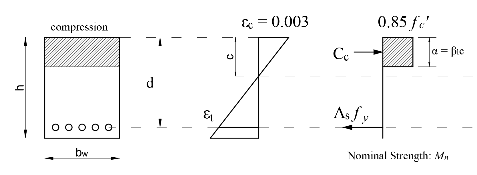
From the equation of equilibrium:
'%3e%3cg transform='translate(167%2c0)'%3e%3cg transform='translate(-13%2c0)'%3e%3cg transform='translate(0%2c-3)'%3e%3cuse xlink:href='%23MJMATHI-43' x='0' y='0'%3e%3c/use%3e%3cuse transform='scale(0.707)' xlink:href='%23MJMATHI-73' x='1011' y='-213'%3e%3c/use%3e%3cuse xlink:href='%23MJMAIN-3D' x='1425' y='0'%3e%3c/use%3e%3cg transform='translate(2481%2c0)'%3e%3cuse xlink:href='%23MJMATHI-43' x='0' y='0'%3e%3c/use%3e%3cuse transform='scale(0.707)' xlink:href='%23MJMATHI-63' x='1011' y='-213'%3e%3c/use%3e%3c/g%3e%3cg transform='translate(6936%2c0)'%3e%3cuse xlink:href='%23MJMATHI-41' x='0' y='0'%3e%3c/use%3e%3cuse transform='scale(0.707)' xlink:href='%23MJMATHI-73' x='1061' y='-213'%3e%3c/use%3e%3c/g%3e%3cg transform='translate(8119%2c0)'%3e%3cuse xlink:href='%23MJMATHI-66' x='0' y='0'%3e%3c/use%3e%3cuse transform='scale(0.707)' xlink:href='%23MJMATHI-79' x='693' y='-213'%3e%3c/use%3e%3c/g%3e%3cuse xlink:href='%23MJMAIN-3D' x='9339' y='0'%3e%3c/use%3e%3cg transform='translate(10395%2c0)'%3e%3cuse xlink:href='%23MJMAIN-30'%3e%3c/use%3e%3cuse xlink:href='%23MJMAIN-2E' x='500' y='0'%3e%3c/use%3e%3cuse xlink:href='%23MJMAIN-38' x='779' y='0'%3e%3c/use%3e%3cuse xlink:href='%23MJMAIN-35' x='1279' y='0'%3e%3c/use%3e%3c/g%3e%3cg transform='translate(12175%2c0)'%3e%3cuse xlink:href='%23MJMATHI-66' x='0' y='0'%3e%3c/use%3e%3cuse transform='scale(0.707)' xlink:href='%23MJMAIN-2032' x='804' y='445'%3e%3c/use%3e%3cuse transform='scale(0.707)' xlink:href='%23MJMATHI-63' x='693' y='-211'%3e%3c/use%3e%3c/g%3e%3cuse xlink:href='%23MJMAIN-28' x='13072' y='0'%3e%3c/use%3e%3cg transform='translate(13462%2c0)'%3e%3cuse xlink:href='%23MJMATHI-62' x='0' y='0'%3e%3c/use%3e%3cuse transform='scale(0.707)' xlink:href='%23MJMATHI-77' x='607' y='-213'%3e%3c/use%3e%3c/g%3e%3cuse xlink:href='%23MJMATHI-3B1' x='14498' y='0'%3e%3c/use%3e%3cuse xlink:href='%23MJMAIN-29' x='15138' y='0'%3e%3c/use%3e%3c/g%3e%3c/g%3e%3c/g%3e%3c/g%3e%3c/svg%3e)
Nominal flexural strength Mn:
'%3e%3cg transform='translate(167%2c0)'%3e%3cg transform='translate(-13%2c0)'%3e%3cg transform='translate(0%2c48)'%3e%3cuse xlink:href='%23MJMATHI-4D' x='0' y='0'%3e%3c/use%3e%3cuse transform='scale(0.707)' xlink:href='%23MJMATHI-6E' x='1372' y='-213'%3e%3c/use%3e%3cuse xlink:href='%23MJMAIN-3D' x='1772' y='0'%3e%3c/use%3e%3cg transform='translate(2829%2c0)'%3e%3cuse xlink:href='%23MJMAIN-30'%3e%3c/use%3e%3cuse xlink:href='%23MJMAIN-2E' x='500' y='0'%3e%3c/use%3e%3cuse xlink:href='%23MJMAIN-38' x='779' y='0'%3e%3c/use%3e%3cuse xlink:href='%23MJMAIN-35' x='1279' y='0'%3e%3c/use%3e%3c/g%3e%3cg transform='translate(4609%2c0)'%3e%3cuse xlink:href='%23MJMATHI-66' x='0' y='0'%3e%3c/use%3e%3cuse transform='scale(0.707)' xlink:href='%23MJMAIN-2032' x='804' y='445'%3e%3c/use%3e%3cuse transform='scale(0.707)' xlink:href='%23MJMATHI-63' x='693' y='-211'%3e%3c/use%3e%3c/g%3e%3cuse xlink:href='%23MJMAIN-28' x='5506' y='0'%3e%3c/use%3e%3cg transform='translate(5895%2c0)'%3e%3cuse xlink:href='%23MJMATHI-62' x='0' y='0'%3e%3c/use%3e%3cuse transform='scale(0.707)' xlink:href='%23MJMATHI-77' x='607' y='-213'%3e%3c/use%3e%3c/g%3e%3cuse xlink:href='%23MJMATHI-3B1' x='6931' y='0'%3e%3c/use%3e%3cuse xlink:href='%23MJMAIN-29' x='7572' y='0'%3e%3c/use%3e%3cuse xlink:href='%23MJMAIN-D7' x='8184' y='0'%3e%3c/use%3e%3cuse xlink:href='%23MJMAIN-28' x='9184' y='0'%3e%3c/use%3e%3cuse xlink:href='%23MJMATHI-64' x='9574' y='0'%3e%3c/use%3e%3cuse xlink:href='%23MJMAIN-2212' x='10320' y='0'%3e%3c/use%3e%3cg transform='translate(11098%2c0)'%3e%3cg transform='translate(342%2c0)'%3e%3crect stroke='none' width='572' height='60' x='0' y='220'%3e%3c/rect%3e%3cuse transform='scale(0.707)' xlink:href='%23MJMATHI-3B1' x='84' y='613'%3e%3c/use%3e%3cuse transform='scale(0.707)' xlink:href='%23MJMAIN-32' x='154' y='-562'%3e%3c/use%3e%3c/g%3e%3c/g%3e%3cuse xlink:href='%23MJMAIN-29' x='12133' y='0'%3e%3c/use%3e%3cuse xlink:href='%23MJMATHI-6F' x='15578' y='0'%3e%3c/use%3e%3cuse xlink:href='%23MJMATHI-72' x='16064' y='0'%3e%3c/use%3e%3cg transform='translate(19571%2c0)'%3e%3cuse xlink:href='%23MJMATHI-4D' x='0' y='0'%3e%3c/use%3e%3cuse transform='scale(0.707)' xlink:href='%23MJMATHI-6E' x='1372' y='-213'%3e%3c/use%3e%3c/g%3e%3cuse xlink:href='%23MJMAIN-3D' x='21344' y='0'%3e%3c/use%3e%3cg transform='translate(22400%2c0)'%3e%3cuse xlink:href='%23MJMATHI-41' x='0' y='0'%3e%3c/use%3e%3cuse transform='scale(0.707)' xlink:href='%23MJMATHI-73' x='1061' y='-213'%3e%3c/use%3e%3c/g%3e%3cg transform='translate(23582%2c0)'%3e%3cuse xlink:href='%23MJMATHI-66' x='0' y='0'%3e%3c/use%3e%3cuse transform='scale(0.707)' xlink:href='%23MJMATHI-79' x='693' y='-213'%3e%3c/use%3e%3c/g%3e%3cuse xlink:href='%23MJMAIN-D7' x='24747' y='0'%3e%3c/use%3e%3cuse xlink:href='%23MJMAIN-28' x='25748' y='0'%3e%3c/use%3e%3cuse xlink:href='%23MJMATHI-64' x='26137' y='0'%3e%3c/use%3e%3cuse xlink:href='%23MJMAIN-2212' x='26883' y='0'%3e%3c/use%3e%3cg transform='translate(27661%2c0)'%3e%3cg transform='translate(342%2c0)'%3e%3crect stroke='none' width='572' height='60' x='0' y='220'%3e%3c/rect%3e%3cuse transform='scale(0.707)' xlink:href='%23MJMATHI-3B1' x='84' y='613'%3e%3c/use%3e%3cuse transform='scale(0.707)' xlink:href='%23MJMAIN-32' x='154' y='-562'%3e%3c/use%3e%3c/g%3e%3c/g%3e%3cuse xlink:href='%23MJMAIN-29' x='28696' y='0'%3e%3c/use%3e%3c/g%3e%3c/g%3e%3c/g%3e%3c/g%3e%3c/svg%3e)
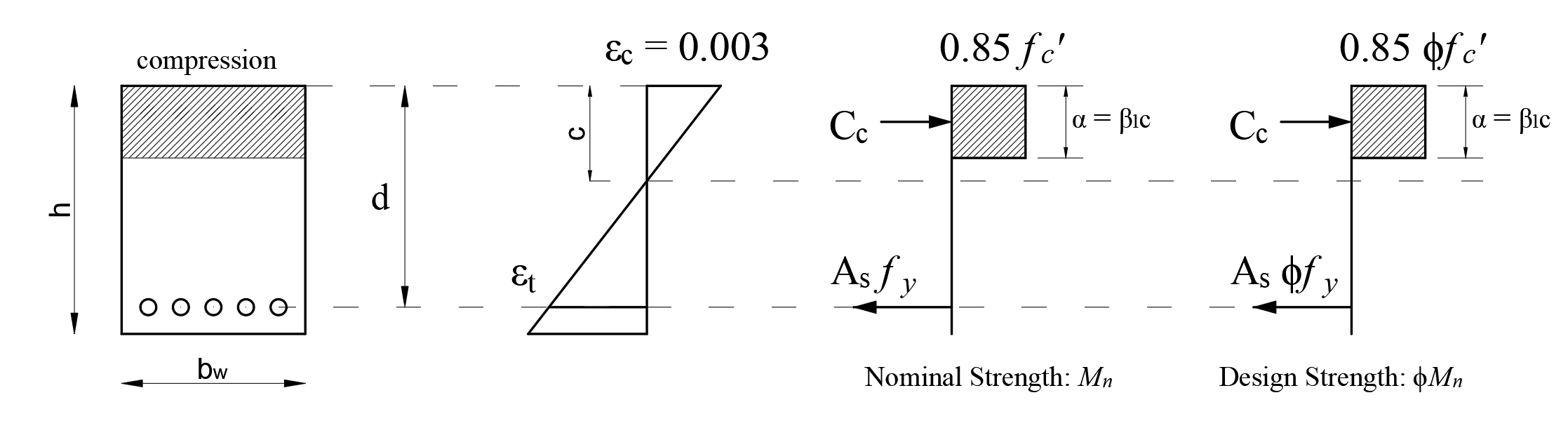
According to ACI 22.1.3, the design strength of a section is taken as the nominal strength multiplied by the applicable strength reduction factor ϕ. Therefore, the design force is ϕMn.
The difference between Design Strength ϕMn and Nominal Strength Mn is indicated in the figure below.
Using the equations above, the area of tensile reinforcement can be found as,
'%3e%3cg transform='translate(167%2c0)'%3e%3cg transform='translate(-13%2c0)'%3e%3cg transform='translate(0%2c302)'%3e%3cuse xlink:href='%23MJMATHI-41' x='0' y='0'%3e%3c/use%3e%3cuse transform='scale(0.707)' xlink:href='%23MJMATHI-73' x='1061' y='-213'%3e%3c/use%3e%3cuse xlink:href='%23MJMAIN-2265' x='1460' y='0'%3e%3c/use%3e%3cg transform='translate(2238%2c0)'%3e%3cg transform='translate(397%2c0)'%3e%3crect stroke='none' width='3670' height='60' x='0' y='220'%3e%3c/rect%3e%3cg transform='translate(1313%2c537)'%3e%3cuse transform='scale(0.707)' xlink:href='%23MJMATHI-4D' x='0' y='0'%3e%3c/use%3e%3cuse transform='scale(0.5)' xlink:href='%23MJMATHI-75' x='1372' y='-213'%3e%3c/use%3e%3c/g%3e%3cg transform='translate(60%2c-776)'%3e%3cuse transform='scale(0.707)' xlink:href='%23MJMATHI-3D5' x='0' y='0'%3e%3c/use%3e%3cg transform='translate(421%2c0)'%3e%3cuse transform='scale(0.707)' xlink:href='%23MJMATHI-66' x='0' y='0'%3e%3c/use%3e%3cuse transform='scale(0.5)' xlink:href='%23MJMATHI-79' x='693' y='-342'%3e%3c/use%3e%3c/g%3e%3cuse xlink:href='%23MJSZ1-28' x='1088' y='-1'%3e%3c/use%3e%3cuse transform='scale(0.707)' xlink:href='%23MJMATHI-64' x='2187' y='0'%3e%3c/use%3e%3cuse transform='scale(0.707)' xlink:href='%23MJMAIN-2212' x='2710' y='0'%3e%3c/use%3e%3cg transform='translate(2467%2c0)'%3e%3cg transform='translate(120%2c0)'%3e%3crect stroke='none' width='384' height='60' x='0' y='146'%3e%3c/rect%3e%3cuse transform='scale(0.5)' xlink:href='%23MJMATHI-61' x='119' y='715'%3e%3c/use%3e%3cuse transform='scale(0.5)' xlink:href='%23MJMAIN-32' x='134' y='-665'%3e%3c/use%3e%3c/g%3e%3c/g%3e%3cuse xlink:href='%23MJSZ1-29' x='3091' y='-1'%3e%3c/use%3e%3c/g%3e%3c/g%3e%3c/g%3e%3c/g%3e%3c/g%3e%3c/g%3e%3c/g%3e%3c/svg%3e)
The required tensile reinforcement area is checked for each factored moment.
Shear Design for Columns of Earthquake-Resistant Structures
Ordinary moment frames
According to ACI 18.3.2;
-
Beams should have a minimum of two continuous bars at the top and bottom faces.
-
The area of continuous bottom bars should not be less than one-fourth of the maximum area of the bottom bars along the span. These bars should be anchored to develop fy in tension at the face of support.
Intermediate moment frames
According to ACI 18.4.2.1;
-
Beams should have a minimum of two continuous bars at the top and bottom faces.
-
The area of continuous bottom bars should not be less than one-fourth of the maximum area of the bottom bars along the span. These bars should be anchored to develop fy in tension at the face of support.
According to ACI 18.4.2.2;
-
The positive moment strength at the face of the joint should be greater than one-third of the negative moment strength provided at that face of the joint.
-
Along the length of the beam, both the positive and the negative moment strength at any section should be greater than one-fifth of the maximum moment strength provided at the face of either joint.
Special moment frames
Beams of special moment frames shall frame into columns of special moment frames.
According to ACI 18.6.3.1;
-
Beams should have a minimum of two continuous bars at the top and bottom faces.
-
Both top and bottom longitudinal reinforcement areas at any section should satisfy the minimum reinforcement area requirement given in Beam Reinforcement Limits per ACI 318-19 with ideCAD title.
-
The reinforcement ratio ρ shall not exceed 0.025 for Grade 60 reinforcement and 0.02 for Grade 80 reinforcement.
According to ACI 18.6.3.2;
-
The positive moment strength at the face of the joint should be greater than one-half of the negative moment strength provided at that face of the joint.
-
Along the length of the beam, both the positive and the negative moment strength at any section should be greater than one-fourth of the maximum moment strength provided at the face of either joint.
Download ideCAD for ACI 318-19
Next Topic