
How does ideCAD design four bolts stiffened end plate connection according to AISC 358-16 & AISC 360-16?
-
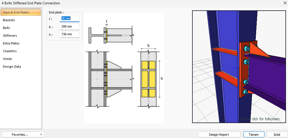
Four bolts stiffened end plate connection is designed automatically according to the AISC 358-16 and AISC 360-16 by the ideCAD Structural.
Symbols
Ab: Non-threaded bolt web characteristic cross-sectional area
Ag: Gross area
An: Net cross-section area
Ae: Effective net cross-sectional area
Avg: Gross area under shear stress
Anv: Net area under shear stress
Ant: Net area under tensile stress
Aw: Cross-section web area
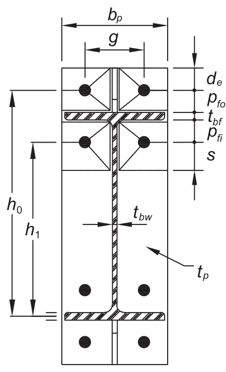
bbf = width of beam flange, in. (mm)
bp = width of end-plate, in. (mm)
d = depth of connecting beam, in. (mm)
g = horizontal distance between bolts, in. (mm)
dh: Bolt hole diameter
Fy: Structural steel characteristic yield strength
Fu: Structural steel characteristic tensile strength
Fyb: Bolt characteristic yield strength
Fub: Bolt characteristic tensile strength
nsp: Number of slip planes
s: Distance between bolt-hole centers
L: Connector distance
Lc: The clear distance between bolt holes
Le: The distance from the center of the bolt hole to the edge of the assembled element
Leh: The horizontal distance from the center of the bolt hole to the edge of the assembled element
Lev: The vertical distance from the center of the bolt hole to the edge of the assembled element
pb = vertical distance between the inner and outer row of bolts in an eight-bolt stiffened connection, in. (mm)
pfi = vertical distance from the inside of a beam tension flange to the nearest inside bolt row, in. (mm)
pfo = vertical distance from the outside of a beam tension flange to the nearest outside bolt row, in. (mm)
tbf = thickness of beam flange, in. (mm)
tp = thickness of end-plate, in. (mm)
Rn: Characteristic strength
Rnt: Characteristic tensile strength
Rnv: Characteristic shear strength
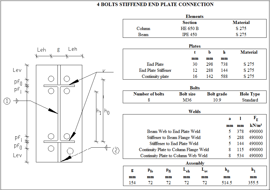
Connection Geometry
GEOMETRY CHECKS
Horizontal Edge Distance
The distance from the center of the hole to the edge of the connected part in the horizontal direction is checked per AISC 360-16.
|
Leh ≥ L e-min |
AISC 360-16 J3.4 |
|
|
|
Leh |
72 mm |
Leh ≥ 2d = 2 * 30 = 60 mm conformity check for application |
√ |
|
Le-min |
46 mm |
Minimum distance check according to Table J3.4 |
√ |
Vertical Edge Distance
The distance from the center of the hole to the edge of the connected part in the vertical direction is checked per AISC 360-16.
|
Lev ≥ L e-min |
AISC 360-16 J3.4 |
|
|
|
Lev |
72 mm |
Lev ≥ 2d = 2 * 30 = 60 mm conformity check for application |
√ |
|
Le-min |
46 mm |
Minimum distance check according to Table J3.4 |
√ |
Beam Web to End Plate Weld Size
The minimum size of fillet welds is checked according to AISC 360-16 Table J2.4
|
w ≥ wmin |
AISC 360-16 |
|
|
|
w |
7.072 mm |
|
√ |
|
wmin |
5 mm |
Table J2.4 |
√ |
Stiffener to Beam Flange Weld Size
The minimum size of fillet welds is checked according to AISC 360-16 Table J2.4
|
w ≥ wmin |
AISC 360-16 |
|
|
|
w |
7.072 mm |
|
√ |
|
wmin |
5 mm |
Table J2.4 |
√ |
Stiffener to End Plate Weld Size
The minimum size welds are checked according to AISC 360-16 Table J2.4
|
w ≥ wmin |
AISC 360-16 |
|
|
|
w |
7.072 mm |
|
√ |
|
wmin |
5 mm |
Table J2.4 |
√ |
Continuity Plate to Column Flange Weld Size
The minimum size welds are checked according to AISC 360-16 Table J2.4
|
w ≥ wmin |
AISC 360-16 |
|
|
|
w |
11.315 mm |
|
√ |
|
wmin |
6 mm |
Table J2.4 |
√ |
Continuity Plate to Column Web Weld Size
The minimum size welds are checked according to AISC 360-16 Table J2.4
|
w ≥ wmin |
AISC 360-16 |
|
|
|
w |
11.315 mm |
|
√ |
|
wmin |
6 mm |
Table J2.4 |
√ |
Prequalification Limits (AISC 358-16 Table 6.1)
All end-plate moment connection configurations should satisfy these beam and column limitations. Beam and column limitations are given in AISC 358-16 Table 6.1.
|
Beam span / Beam cross-section height |
9144 mm /450 mm=20.32 |
≥7.0 |
|
End plate thickness, tp |
32 mm |
13≤tp ≤38 |
|
End plate width, bp |
290 mm |
178≤ bp ≤ 273 |
|
Horizontal distance between bolts, g |
150 mm |
83≤g≤152 |
|
pfi |
60 mm |
44≤pfi ≤140 |
|
pfo |
60 mm |
44≤pfo ≤140 |
|
Beam depth, db |
450 mm |
349≤db≤610 |
|
Beam flange thickness, tbf |
15 mm |
10≤tbf ≤19 |
|
Beam flange width, bbf |
190 |
152≤bbf ≤229 |
|
Column depth |
650 |
≤ 920 mm |
|
Bolt grade |
10.9 |
8.8 - 10.9 |
|
Min yield stress of the end plate material |
275 MPa |
235 /275 / 355 MPa |
|
Flange plate weld |
CJP |
CJP |
STRENGTH CHECKS
Bolt diameter
The required bolt diameter, db, for four bolts stiffened end plate connection is checked according to AISC 358-16 §6.8
|
Muc |
821.813 kNm |
AISC 358-16 (6.8-3) |
|
Ft |
750000 kN/m2 |
|
|
ho |
|
|
|
h1 |
|
|
|
db |
|
|
|
Required |
Available |
Ratio |
Control |
|---|---|---|---|
|
29.825 mm |
36 mm |
0.829 |
√ |
End Plate Thickness
The required end plate thickness, tp, for four bolts stiffened end plate connection is checked according to AISC 358-16 §6.8
|
Muc |
821.813kNm |
AISC 358-16 (6.8-5) |
|
Fyp |
275000 kN/m2 |
|
|
s |
|
|
|
Yp |
|
|
|
Yp |
|
|
|
tp |
|
|
|
Required |
Available |
Ratio |
Control |
|---|---|---|---|
|
27.327 mm |
30 mm |
0.911 |
√ |
End Plate Stiffener Thickness
The required stiffener thickness, tb, for four bolts stiffened end plate connection is checked according to AISC 358-16 §6.8
|
tbw |
9 mm |
AISC 358-16 (6.8-9) |
|
Fyb |
275000 kN/m2 |
|
|
Fys |
275000 kN/m2 |
|
|
ts |
12 mm |
|
|
|
|
|
|
|
|
|
|
Required |
Available |
Ratio |
Control |
|---|---|---|---|
|
9 mm |
12 mm |
0.750 |
√ |
End Plate Stiffener Local Buckling
Stiffener local buckling limit state for four bolts stiffened end plate connection is checked according to AISC 358-16 §6.8
|
hs |
144 mm |
AISC 358-16 (6.8-10) |
|
ts |
12 mm |
|
|
E |
200000000 kN/m2 |
|
|
Fys |
275000 kN/m2 |
|
|
|
|
|
|
|
|
|
|
Required |
Available |
Ratio |
Control |
|---|---|---|---|
|
12 |
15.102 |
0.795 |
√ |
Stiffener to Beam Flange Weld Size
The required end weld size for four bolts stiffened end plate connection is checked.
|
Fys |
275000 kN/m2 |
AISC DG 4-2 nd 3.2.10 |
|
ts |
12 mm |
|
|
Fe |
490000 kN/m2 |
|
|
w |
|
|
|
Required |
Available |
Ratio |
Control |
|---|---|---|---|
|
6.35 |
7.072 |
0.898 |
√ |
Stiffener to End Plate Weld Size
The required end weld size for four bolts stiffened end plate connection is checked.
|
Fys |
275000 kN/m2 |
AISC DG 4-2 nd 3.2.10 |
|
ts |
12 mm |
|
|
Fe |
490000 kN/m2 |
|
|
w |
|
|
|
Required |
Available |
Ratio |
Control |
|---|---|---|---|
|
6.35 |
7.072 |
0.898 |
√ |
Bolt Shear Check
The shear limit state of end plate bolts is checked according to AISC 360-16.
|
Ab |
|
AISC 358-16 6.8.11 |
|
Fn |
|
|
|
Rn |
|
|
|
ΦRn |
|
|
|
Required |
Available |
Ratio |
Control |
|---|---|---|---|
|
271.371 kN |
1648.959 kN |
0.165 |
√ |
Bolt Bearing on End Plate
Bearing strength limit states of the connection plate that are “shear tear out” and “ovalization of bolt hole” for both end and inner bolts are checked according to AISC 360-16.
|
dh |
36+3=39 mm |
|
|
Lc,edge |
|
|
|
Rn |
|
AISC 358-16 6.8-12 |
|
Rn-edge |
|
|
|
Lc,spacing |
|
|
|
Rn-spacing |
|
|
|
Rn |
|
|
|
ΦRn |
|
|
|
Required |
Available |
Ratio |
Control |
|---|---|---|---|
|
271.371 kN |
3307.716 kN |
0.082 |
√ |
Bolt Bearing on Column Flange
Bearing strength limit states of the connection plate that are “shear tear out” and “ovalization of bolt hole” for both end and inner bolts are checked according to AISC 360-16.
|
db |
36 mm |
|
|
Rn |
|
AISC 358-16 6.8-12 |
|
Rn-edge |
|
|
|
Lc,spacing |
|
|
|
Rn-spacing |
|
|
|
Rn |
|
|
|
ΦRn |
|
|
|
Required |
Available |
Ratio |
Control |
|---|---|---|---|
|
271.371 kN |
3953.318 kN |
0.069 |
√ |
Beam Web to End Plate Weld Size
The required end weld size for four bolts stiffened end plate connection is checked according to AISC 358-16 §6.7
|
Fyp |
275000 kN/m2 |
AISC 358-16 (6.7.6) 3 |
|
tbw |
9 mm |
|
|
F e |
490000 kN/m2 |
|
|
w |
|
|
|
Required |
Available |
Ratio |
Control |
|---|---|---|---|
|
4.763 mm |
7.072 mm |
0.673 |
√ |
Column Flange Thickness
The required column flange thickness, tcf, for four bolts unstiffened end plate connection is checked according to AISC 358-16 §6.8
|
Muc |
821.813 kNm |
AISC 358-16 (6.8-13) |
|
Fyp |
275 N/mm2 |
|
|
s |
|
|
|
c |
|
|
|
Yc |
|
|
|
Yc |
|
|
|
tcf |
|
|
|
Required |
Available |
Ratio |
Control |
|---|---|---|---|
|
25.618 mm |
31 mm |
0.826 |
√ |
Column Panel Zone Shear
Yielding of the column panel zone for four bolts unstiffened end plate connection is checked according to AISC 360-16 §J.10
|
Pr |
355.597 kN |
AISC 360-16 J10-9 |
|
Py |
|
|
|
Fy |
275000 kN/m2 |
|
|
Ag |
28634.759 mm2 |
|
|
dc |
650 mm |
|
|
tw |
16 mm |
|
|
Rn |
|
|
|
ΦRn |
|
|
|
Required |
Available |
Ratio |
Control |
|---|---|---|---|
|
1673.526 kN |
1716 kN |
0.975 |
√ |
Panel Zone Thickness
The required panel zone thickness for four bolts unstiffened end plate connection is checked according to AISC 358-16.
|
tmin≥u/180 |
|
|
|
t min = tw |
16 mm |
|
|
tw |
16 mm |
|
|
u |
2016 mm |
|
|
Required |
Available |
Ratio |
Control |
|---|---|---|---|
|
11.2 mm |
16 mm |
0.700 |
√ |
Next Topic