
How does ideCAD design castellated beams according to AISC 360-16?
-
Castellated steel beam design is made automatically according to AISC 360-16.
-
The user can change steel beam design settings.
Symbols
Cb : The lateral-torsional buckling modification factor
Zx = Plastic section modulus about the x-axis, in.3 (mm3)
E: Modulus of elasticity of steel = 29,000 ksi (200 000 MPa)
Fy : Specified minimum yield stress of the type of steel being used, ksi
Fcr : Critical stress
K : Effective length factor
L: Laterally unbraced length of the member
Pr: Required axial force resistance for LRFD or ASD load combinations
Pc: Strength of axial compressive force available according to Section E
Mr: Required bending moment strength for LRFD or ASD load combinations
Mc: current bending moment strength according to Section F
r: Radius of gyration
λ: Width-to-thickness ratio for the element as defined in Section B4.1
λr : Limiting width-to-thickness ratio as defined in Table B4.1a
Lb : Length between points that are either braced against lateral displacement of the compression flange or braced against twist of the cross-section, in. (mm)
Lp : The limiting laterally unbraced length for the limit state of yielding, in. (mm)
Lr : The limiting unbraced length for the limit state of inelastic lateral-torsional buckling, in. (mm),
Mn : The nominal flexural strength
Mp : Plastic bending moment
Sx : Elastic section modulus taken about the x-axis, in.3 (mm3)
Castellated Beam Sections
Castellated hexagonal, castellated circular, castellated octagonal, and angelina sections can be defined. Castellated hexagonal and castellated circular sections are designed.
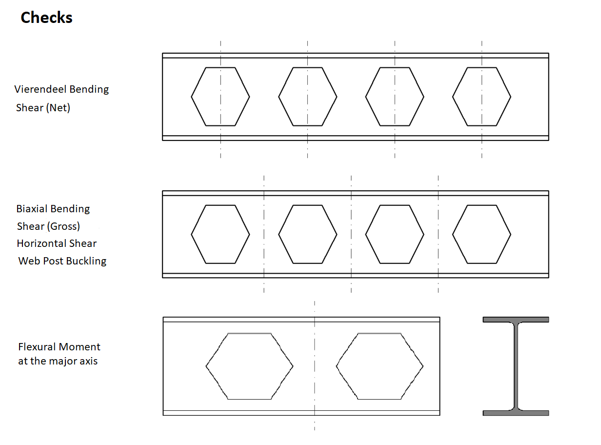
Biaxial Bending and Axial Force
Yielding Limit State
For the yield limit state, the nominal flexural strength, Mn, is calculated using the equation below by AISC 360-16.
'%3e%3cg transform='translate(167%2c0)'%3e%3cg transform='translate(-13%2c0)'%3e%3cg transform='translate(0%2c-3)'%3e%3cuse xlink:href='%23MJMATHI-4D' x='0' y='0'%3e%3c/use%3e%3cuse transform='scale(0.707)' xlink:href='%23MJMATHI-6E' x='1372' y='-213'%3e%3c/use%3e%3cuse xlink:href='%23MJMAIN-3D' x='1772' y='0'%3e%3c/use%3e%3cg transform='translate(2829%2c0)'%3e%3cuse xlink:href='%23MJMATHI-4D' x='0' y='0'%3e%3c/use%3e%3cuse transform='scale(0.707)' xlink:href='%23MJMATHI-70' x='1372' y='-213'%3e%3c/use%3e%3c/g%3e%3cuse xlink:href='%23MJMAIN-3D' x='4533' y='0'%3e%3c/use%3e%3cg transform='translate(5589%2c0)'%3e%3cuse xlink:href='%23MJMATHI-46' x='0' y='0'%3e%3c/use%3e%3cuse transform='scale(0.707)' xlink:href='%23MJMATHI-79' x='910' y='-213'%3e%3c/use%3e%3c/g%3e%3cg transform='translate(6685%2c0)'%3e%3cuse xlink:href='%23MJMATHI-5A' x='0' y='0'%3e%3c/use%3e%3cuse transform='scale(0.707)' xlink:href='%23MJMATHI-78' x='966' y='-213'%3e%3c/use%3e%3c/g%3e%3cuse xlink:href='%23MJMAIN-28' x='17873' y='0'%3e%3c/use%3e%3cuse xlink:href='%23MJMATHI-46' x='18262' y='0'%3e%3c/use%3e%3cuse xlink:href='%23MJMAIN-32' x='19012' y='0'%3e%3c/use%3e%3cuse xlink:href='%23MJMAIN-2212' x='19735' y='0'%3e%3c/use%3e%3cuse xlink:href='%23MJMAIN-31' x='20735' y='0'%3e%3c/use%3e%3cuse xlink:href='%23MJMAIN-29' x='21236' y='0'%3e%3c/use%3e%3c/g%3e%3c/g%3e%3c/g%3e%3c/g%3e%3c/svg%3e)
-
When Lb ≤ Lp
-
When Lp < Lb ≤ Lr
'%3e%3cg transform='translate(167%2c0)'%3e%3cg transform='translate(-13%2c0)'%3e%3cuse xlink:href='%23MJMATHI-4D' x='0' y='0'%3e%3c/use%3e%3cuse transform='scale(0.707)' xlink:href='%23MJMATHI-6E' x='1372' y='-213'%3e%3c/use%3e%3cuse xlink:href='%23MJMAIN-3D' x='1772' y='0'%3e%3c/use%3e%3cg transform='translate(2829%2c0)'%3e%3cuse xlink:href='%23MJMATHI-43' x='0' y='0'%3e%3c/use%3e%3cuse transform='scale(0.707)' xlink:href='%23MJMATHI-62' x='1011' y='-213'%3e%3c/use%3e%3c/g%3e%3cuse xlink:href='%23MJSZ4-5B' x='3948' y='-1'%3e%3c/use%3e%3cg transform='translate(4531%2c0)'%3e%3cuse xlink:href='%23MJMATHI-4D' x='0' y='0'%3e%3c/use%3e%3cuse transform='scale(0.707)' xlink:href='%23MJMATHI-70' x='1372' y='-213'%3e%3c/use%3e%3c/g%3e%3cuse xlink:href='%23MJMAIN-2212' x='6180' y='0'%3e%3c/use%3e%3cuse xlink:href='%23MJMAIN-28' x='7181' y='0'%3e%3c/use%3e%3cg transform='translate(7570%2c0)'%3e%3cuse xlink:href='%23MJMATHI-4D' x='0' y='0'%3e%3c/use%3e%3cuse transform='scale(0.707)' xlink:href='%23MJMATHI-70' x='1372' y='-213'%3e%3c/use%3e%3c/g%3e%3cuse xlink:href='%23MJMAIN-2212' x='9219' y='0'%3e%3c/use%3e%3cg transform='translate(10220%2c0)'%3e%3cuse xlink:href='%23MJMAIN-30'%3e%3c/use%3e%3cuse xlink:href='%23MJMAIN-2E' x='500' y='0'%3e%3c/use%3e%3cuse xlink:href='%23MJMAIN-37' x='779' y='0'%3e%3c/use%3e%3c/g%3e%3cg transform='translate(11499%2c0)'%3e%3cuse xlink:href='%23MJMATHI-46' x='0' y='0'%3e%3c/use%3e%3cuse transform='scale(0.707)' xlink:href='%23MJMATHI-79' x='910' y='-213'%3e%3c/use%3e%3c/g%3e%3cg transform='translate(12595%2c0)'%3e%3cuse xlink:href='%23MJMATHI-53' x='0' y='0'%3e%3c/use%3e%3cuse transform='scale(0.707)' xlink:href='%23MJMATHI-78' x='867' y='-213'%3e%3c/use%3e%3c/g%3e%3cuse xlink:href='%23MJMAIN-29' x='13713' y='0'%3e%3c/use%3e%3cuse xlink:href='%23MJSZ3-28' x='14102' y='-1'%3e%3c/use%3e%3cg transform='translate(14839%2c0)'%3e%3cg transform='translate(120%2c0)'%3e%3crect stroke='none' width='3581' height='60' x='0' y='220'%3e%3c/rect%3e%3cg transform='translate(67%2c781)'%3e%3cuse xlink:href='%23MJMATHI-4C' x='0' y='0'%3e%3c/use%3e%3cuse transform='scale(0.707)' xlink:href='%23MJMATHI-62' x='963' y='-213'%3e%3c/use%3e%3cuse xlink:href='%23MJMAIN-2212' x='1307' y='0'%3e%3c/use%3e%3cg transform='translate(2308%2c0)'%3e%3cuse xlink:href='%23MJMATHI-4C' x='0' y='0'%3e%3c/use%3e%3cuse transform='scale(0.707)' xlink:href='%23MJMATHI-70' x='963' y='-213'%3e%3c/use%3e%3c/g%3e%3c/g%3e%3cg transform='translate(60%2c-686)'%3e%3cuse xlink:href='%23MJMATHI-4C' x='0' y='0'%3e%3c/use%3e%3cuse transform='scale(0.707)' xlink:href='%23MJMATHI-72' x='963' y='-213'%3e%3c/use%3e%3cuse xlink:href='%23MJMAIN-2212' x='1322' y='0'%3e%3c/use%3e%3cg transform='translate(2323%2c0)'%3e%3cuse xlink:href='%23MJMATHI-4C' x='0' y='0'%3e%3c/use%3e%3cuse transform='scale(0.707)' xlink:href='%23MJMATHI-70' x='963' y='-213'%3e%3c/use%3e%3c/g%3e%3c/g%3e%3c/g%3e%3c/g%3e%3cuse xlink:href='%23MJSZ3-29' x='18660' y='-1'%3e%3c/use%3e%3cuse xlink:href='%23MJSZ4-5D' x='19397' y='-1'%3e%3c/use%3e%3cuse xlink:href='%23MJMAIN-2264' x='20258' y='0'%3e%3c/use%3e%3cg transform='translate(21314%2c0)'%3e%3cuse xlink:href='%23MJMATHI-4D' x='0' y='0'%3e%3c/use%3e%3cuse transform='scale(0.707)' xlink:href='%23MJMATHI-70' x='1372' y='-213'%3e%3c/use%3e%3c/g%3e%3cuse xlink:href='%23MJMAIN-28' x='32741' y='0'%3e%3c/use%3e%3cuse xlink:href='%23MJMATHI-46' x='33130' y='0'%3e%3c/use%3e%3cuse xlink:href='%23MJMAIN-32' x='33880' y='0'%3e%3c/use%3e%3cuse xlink:href='%23MJMAIN-2212' x='34602' y='0'%3e%3c/use%3e%3cuse xlink:href='%23MJMAIN-32' x='35603' y='0'%3e%3c/use%3e%3cuse xlink:href='%23MJMAIN-29' x='36104' y='0'%3e%3c/use%3e%3c/g%3e%3c/g%3e%3c/g%3e%3c/svg%3e)
-
When Lb > Lr
'%3e%3cg transform='translate(167%2c0)'%3e%3cg transform='translate(-13%2c0)'%3e%3cg transform='translate(0%2c-7)'%3e%3cuse xlink:href='%23MJMATHI-4D' x='0' y='0'%3e%3c/use%3e%3cuse transform='scale(0.707)' xlink:href='%23MJMATHI-6E' x='1372' y='-213'%3e%3c/use%3e%3cuse xlink:href='%23MJMAIN-3D' x='1772' y='0'%3e%3c/use%3e%3cg transform='translate(2829%2c0)'%3e%3cuse xlink:href='%23MJMATHI-46' x='0' y='0'%3e%3c/use%3e%3cg transform='translate(643%2c-150)'%3e%3cuse transform='scale(0.707)' xlink:href='%23MJMATHI-63' x='0' y='0'%3e%3c/use%3e%3cuse transform='scale(0.707)' xlink:href='%23MJMATHI-72' x='433' y='0'%3e%3c/use%3e%3c/g%3e%3c/g%3e%3cg transform='translate(4198%2c0)'%3e%3cuse xlink:href='%23MJMATHI-53' x='0' y='0'%3e%3c/use%3e%3cuse transform='scale(0.707)' xlink:href='%23MJMATHI-78' x='867' y='-213'%3e%3c/use%3e%3c/g%3e%3cuse xlink:href='%23MJMAIN-2264' x='5594' y='0'%3e%3c/use%3e%3cg transform='translate(6650%2c0)'%3e%3cuse xlink:href='%23MJMATHI-4D' x='0' y='0'%3e%3c/use%3e%3cuse transform='scale(0.707)' xlink:href='%23MJMATHI-70' x='1372' y='-213'%3e%3c/use%3e%3c/g%3e%3cuse xlink:href='%23MJMAIN-28' x='18077' y='0'%3e%3c/use%3e%3cuse xlink:href='%23MJMATHI-46' x='18466' y='0'%3e%3c/use%3e%3cuse xlink:href='%23MJMAIN-32' x='19216' y='0'%3e%3c/use%3e%3cuse xlink:href='%23MJMAIN-2212' x='19939' y='0'%3e%3c/use%3e%3cuse xlink:href='%23MJMAIN-33' x='20939' y='0'%3e%3c/use%3e%3cuse xlink:href='%23MJMAIN-29' x='21440' y='0'%3e%3c/use%3e%3c/g%3e%3c/g%3e%3c/g%3e%3c/g%3e%3c/svg%3e)
Axial Force
The axial compression capacity for the web part of the castellated beam is calculated as follows.
'%3e%3cg transform='translate(167%2c0)'%3e%3cg transform='translate(-13%2c0)'%3e%3cg transform='translate(0%2c-3)'%3e%3cuse xlink:href='%23MJMATHI-50' x='0' y='0'%3e%3c/use%3e%3cuse transform='scale(0.707)' xlink:href='%23MJMATHI-6E' x='908' y='-213'%3e%3c/use%3e%3cuse xlink:href='%23MJMAIN-3D' x='1444' y='0'%3e%3c/use%3e%3cg transform='translate(2501%2c0)'%3e%3cuse xlink:href='%23MJMATHI-46' x='0' y='0'%3e%3c/use%3e%3cg transform='translate(643%2c-150)'%3e%3cuse transform='scale(0.707)' xlink:href='%23MJMATHI-63' x='0' y='0'%3e%3c/use%3e%3cuse transform='scale(0.707)' xlink:href='%23MJMATHI-72' x='433' y='0'%3e%3c/use%3e%3c/g%3e%3c/g%3e%3cg transform='translate(3870%2c0)'%3e%3cuse xlink:href='%23MJMATHI-41' x='0' y='0'%3e%3c/use%3e%3cuse transform='scale(0.707)' xlink:href='%23MJMATHI-67' x='1061' y='-213'%3e%3c/use%3e%3c/g%3e%3cuse xlink:href='%23MJMAIN-28' x='15060' y='0'%3e%3c/use%3e%3cuse xlink:href='%23MJMATHI-45' x='15450' y='0'%3e%3c/use%3e%3cuse xlink:href='%23MJMAIN-33' x='16214' y='0'%3e%3c/use%3e%3cuse xlink:href='%23MJMAIN-2212' x='16937' y='0'%3e%3c/use%3e%3cuse xlink:href='%23MJMAIN-31' x='17938' y='0'%3e%3c/use%3e%3cuse xlink:href='%23MJMAIN-29' x='18438' y='0'%3e%3c/use%3e%3c/g%3e%3c/g%3e%3c/g%3e%3c/g%3e%3c/svg%3e)
The critical stress, Fcr, is calculated as shown below.
-
When
![]()
'%3e%3cg transform='translate(167%2c0)'%3e%3cg transform='translate(-13%2c0)'%3e%3cg transform='translate(0%2c18)'%3e%3cg transform='translate(120%2c0)'%3e%3crect stroke='none' width='1208' height='60' x='0' y='220'%3e%3c/rect%3e%3cg transform='translate(60%2c676)'%3e%3cuse xlink:href='%23MJMATHI-4C' x='0' y='0'%3e%3c/use%3e%3cuse transform='scale(0.707)' xlink:href='%23MJMATHI-63' x='963' y='-213'%3e%3c/use%3e%3c/g%3e%3cuse xlink:href='%23MJMATHI-72' x='378' y='-686'%3e%3c/use%3e%3c/g%3e%3cuse xlink:href='%23MJMAIN-2264' x='1725' y='0'%3e%3c/use%3e%3cg transform='translate(2782%2c0)'%3e%3cuse xlink:href='%23MJMAIN-34'%3e%3c/use%3e%3cuse xlink:href='%23MJMAIN-2E' x='500' y='0'%3e%3c/use%3e%3cuse xlink:href='%23MJMAIN-37' x='779' y='0'%3e%3c/use%3e%3cuse xlink:href='%23MJMAIN-31' x='1279' y='0'%3e%3c/use%3e%3c/g%3e%3cg transform='translate(4562%2c0)'%3e%3cuse xlink:href='%23MJSZ4-221A' x='0' y='-49'%3e%3c/use%3e%3crect stroke='none' width='1455' height='60' x='1000' y='1642'%3e%3c/rect%3e%3cg transform='translate(1000%2c0)'%3e%3cg transform='translate(120%2c0)'%3e%3crect stroke='none' width='1215' height='60' x='0' y='220'%3e%3c/rect%3e%3cuse xlink:href='%23MJMATHI-45' x='225' y='676'%3e%3c/use%3e%3cg transform='translate(60%2c-686)'%3e%3cuse xlink:href='%23MJMATHI-46' x='0' y='0'%3e%3c/use%3e%3cuse transform='scale(0.707)' xlink:href='%23MJMATHI-79' x='910' y='-213'%3e%3c/use%3e%3c/g%3e%3c/g%3e%3c/g%3e%3c/g%3e%3cuse xlink:href='%23MJMAIN-28' x='10628' y='0'%3e%3c/use%3e%3cuse xlink:href='%23MJMATHI-6F' x='11018' y='0'%3e%3c/use%3e%3cuse xlink:href='%23MJMATHI-72' x='11503' y='0'%3e%3c/use%3e%3cg transform='translate(12233%2c0)'%3e%3cg transform='translate(120%2c0)'%3e%3crect stroke='none' width='1215' height='60' x='0' y='220'%3e%3c/rect%3e%3cg transform='translate(60%2c789)'%3e%3cuse xlink:href='%23MJMATHI-46' x='0' y='0'%3e%3c/use%3e%3cuse transform='scale(0.707)' xlink:href='%23MJMATHI-79' x='910' y='-213'%3e%3c/use%3e%3c/g%3e%3cg transform='translate(70%2c-686)'%3e%3cuse xlink:href='%23MJMATHI-46' x='0' y='0'%3e%3c/use%3e%3cuse transform='scale(0.707)' xlink:href='%23MJMATHI-65' x='910' y='-213'%3e%3c/use%3e%3c/g%3e%3c/g%3e%3c/g%3e%3cuse xlink:href='%23MJMAIN-2264' x='13966' y='0'%3e%3c/use%3e%3cg transform='translate(15022%2c0)'%3e%3cuse xlink:href='%23MJMAIN-32'%3e%3c/use%3e%3cuse xlink:href='%23MJMAIN-2E' x='500' y='0'%3e%3c/use%3e%3cuse xlink:href='%23MJMAIN-32' x='779' y='0'%3e%3c/use%3e%3cuse xlink:href='%23MJMAIN-35' x='1279' y='0'%3e%3c/use%3e%3c/g%3e%3cuse xlink:href='%23MJMAIN-29' x='16802' y='0'%3e%3c/use%3e%3c/g%3e%3c/g%3e%3c/g%3e%3c/g%3e%3c/svg%3e)
'%3e%3cg transform='translate(167%2c0)'%3e%3cg transform='translate(-13%2c0)'%3e%3cuse xlink:href='%23MJMATHI-46' x='0' y='0'%3e%3c/use%3e%3cg transform='translate(643%2c-150)'%3e%3cuse transform='scale(0.707)' xlink:href='%23MJMATHI-63' x='0' y='0'%3e%3c/use%3e%3cuse transform='scale(0.707)' xlink:href='%23MJMATHI-72' x='433' y='0'%3e%3c/use%3e%3c/g%3e%3cuse xlink:href='%23MJMAIN-3D' x='1647' y='0'%3e%3c/use%3e%3cuse xlink:href='%23MJSZ3-28' x='2703' y='-1'%3e%3c/use%3e%3cg transform='translate(3439%2c0)'%3e%3cuse xlink:href='%23MJMAIN-30'%3e%3c/use%3e%3cuse xlink:href='%23MJMAIN-2E' x='500' y='0'%3e%3c/use%3e%3cuse xlink:href='%23MJMAIN-36' x='779' y='0'%3e%3c/use%3e%3cuse xlink:href='%23MJMAIN-35' x='1279' y='0'%3e%3c/use%3e%3cuse xlink:href='%23MJMAIN-38' x='1780' y='0'%3e%3c/use%3e%3cg transform='translate(2280%2c527)'%3e%3cg transform='translate(120%2c0)'%3e%3crect stroke='none' width='740' height='60' x='0' y='146'%3e%3c/rect%3e%3cg transform='translate(60%2c530)'%3e%3cuse transform='scale(0.5)' xlink:href='%23MJMATHI-46' x='0' y='0'%3e%3c/use%3e%3cuse transform='scale(0.5)' xlink:href='%23MJMATHI-79' x='643' y='-150'%3e%3c/use%3e%3c/g%3e%3cg transform='translate(67%2c-340)'%3e%3cuse transform='scale(0.5)' xlink:href='%23MJMATHI-46' x='0' y='0'%3e%3c/use%3e%3cuse transform='scale(0.5)' xlink:href='%23MJMATHI-65' x='643' y='-150'%3e%3c/use%3e%3c/g%3e%3c/g%3e%3c/g%3e%3c/g%3e%3cuse xlink:href='%23MJSZ3-29' x='6800' y='-1'%3e%3c/use%3e%3cg transform='translate(7537%2c0)'%3e%3cuse xlink:href='%23MJMATHI-46' x='0' y='0'%3e%3c/use%3e%3cuse transform='scale(0.707)' xlink:href='%23MJMATHI-79' x='910' y='-213'%3e%3c/use%3e%3c/g%3e%3cuse xlink:href='%23MJMAIN-28' x='18632' y='0'%3e%3c/use%3e%3cuse xlink:href='%23MJMATHI-45' x='19022' y='0'%3e%3c/use%3e%3cuse xlink:href='%23MJMAIN-33' x='19786' y='0'%3e%3c/use%3e%3cuse xlink:href='%23MJMAIN-2212' x='20509' y='0'%3e%3c/use%3e%3cuse xlink:href='%23MJMAIN-32' x='21510' y='0'%3e%3c/use%3e%3cuse xlink:href='%23MJMAIN-29' x='22010' y='0'%3e%3c/use%3e%3c/g%3e%3c/g%3e%3c/g%3e%3c/svg%3e)
-
When
![]()
'%3e%3cg transform='translate(167%2c0)'%3e%3cg transform='translate(-13%2c0)'%3e%3cg transform='translate(0%2c18)'%3e%3cg transform='translate(120%2c0)'%3e%3crect stroke='none' width='1208' height='60' x='0' y='220'%3e%3c/rect%3e%3cg transform='translate(60%2c676)'%3e%3cuse xlink:href='%23MJMATHI-4C' x='0' y='0'%3e%3c/use%3e%3cuse transform='scale(0.707)' xlink:href='%23MJMATHI-63' x='963' y='-213'%3e%3c/use%3e%3c/g%3e%3cuse xlink:href='%23MJMATHI-72' x='378' y='-686'%3e%3c/use%3e%3c/g%3e%3cuse xlink:href='%23MJMAIN-3E' x='1725' y='0'%3e%3c/use%3e%3cg transform='translate(2782%2c0)'%3e%3cuse xlink:href='%23MJMAIN-34'%3e%3c/use%3e%3cuse xlink:href='%23MJMAIN-2E' x='500' y='0'%3e%3c/use%3e%3cuse xlink:href='%23MJMAIN-37' x='779' y='0'%3e%3c/use%3e%3cuse xlink:href='%23MJMAIN-31' x='1279' y='0'%3e%3c/use%3e%3c/g%3e%3cg transform='translate(4562%2c0)'%3e%3cuse xlink:href='%23MJSZ4-221A' x='0' y='-49'%3e%3c/use%3e%3crect stroke='none' width='1455' height='60' x='1000' y='1642'%3e%3c/rect%3e%3cg transform='translate(1000%2c0)'%3e%3cg transform='translate(120%2c0)'%3e%3crect stroke='none' width='1215' height='60' x='0' y='220'%3e%3c/rect%3e%3cuse xlink:href='%23MJMATHI-45' x='225' y='676'%3e%3c/use%3e%3cg transform='translate(60%2c-686)'%3e%3cuse xlink:href='%23MJMATHI-46' x='0' y='0'%3e%3c/use%3e%3cuse transform='scale(0.707)' xlink:href='%23MJMATHI-79' x='910' y='-213'%3e%3c/use%3e%3c/g%3e%3c/g%3e%3c/g%3e%3c/g%3e%3cuse xlink:href='%23MJMAIN-28' x='10628' y='0'%3e%3c/use%3e%3cuse xlink:href='%23MJMATHI-6F' x='11018' y='0'%3e%3c/use%3e%3cuse xlink:href='%23MJMATHI-72' x='11503' y='0'%3e%3c/use%3e%3cg transform='translate(12233%2c0)'%3e%3cg transform='translate(120%2c0)'%3e%3crect stroke='none' width='1215' height='60' x='0' y='220'%3e%3c/rect%3e%3cg transform='translate(60%2c789)'%3e%3cuse xlink:href='%23MJMATHI-46' x='0' y='0'%3e%3c/use%3e%3cuse transform='scale(0.707)' xlink:href='%23MJMATHI-79' x='910' y='-213'%3e%3c/use%3e%3c/g%3e%3cg transform='translate(70%2c-686)'%3e%3cuse xlink:href='%23MJMATHI-46' x='0' y='0'%3e%3c/use%3e%3cuse transform='scale(0.707)' xlink:href='%23MJMATHI-65' x='910' y='-213'%3e%3c/use%3e%3c/g%3e%3c/g%3e%3c/g%3e%3cuse xlink:href='%23MJMAIN-3E' x='13966' y='0'%3e%3c/use%3e%3cg transform='translate(15022%2c0)'%3e%3cuse xlink:href='%23MJMAIN-32'%3e%3c/use%3e%3cuse xlink:href='%23MJMAIN-2E' x='500' y='0'%3e%3c/use%3e%3cuse xlink:href='%23MJMAIN-32' x='779' y='0'%3e%3c/use%3e%3cuse xlink:href='%23MJMAIN-35' x='1279' y='0'%3e%3c/use%3e%3c/g%3e%3cuse xlink:href='%23MJMAIN-29' x='16802' y='0'%3e%3c/use%3e%3c/g%3e%3c/g%3e%3c/g%3e%3c/g%3e%3c/svg%3e)
'%3e%3cg transform='translate(167%2c0)'%3e%3cg transform='translate(-13%2c0)'%3e%3cg transform='translate(0%2c-25)'%3e%3cuse xlink:href='%23MJMATHI-46' x='0' y='0'%3e%3c/use%3e%3cg transform='translate(643%2c-150)'%3e%3cuse transform='scale(0.707)' xlink:href='%23MJMATHI-63' x='0' y='0'%3e%3c/use%3e%3cuse transform='scale(0.707)' xlink:href='%23MJMATHI-72' x='433' y='0'%3e%3c/use%3e%3c/g%3e%3cuse xlink:href='%23MJMAIN-3D' x='1647' y='0'%3e%3c/use%3e%3cg transform='translate(2703%2c0)'%3e%3cuse xlink:href='%23MJMAIN-30'%3e%3c/use%3e%3cuse xlink:href='%23MJMAIN-2E' x='500' y='0'%3e%3c/use%3e%3cuse xlink:href='%23MJMAIN-38' x='779' y='0'%3e%3c/use%3e%3cuse xlink:href='%23MJMAIN-37' x='1279' y='0'%3e%3c/use%3e%3cuse xlink:href='%23MJMAIN-37' x='1780' y='0'%3e%3c/use%3e%3c/g%3e%3cg transform='translate(4983%2c0)'%3e%3cuse xlink:href='%23MJMATHI-46' x='0' y='0'%3e%3c/use%3e%3cuse transform='scale(0.707)' xlink:href='%23MJMATHI-65' x='910' y='-213'%3e%3c/use%3e%3c/g%3e%3cuse xlink:href='%23MJMAIN-28' x='16057' y='0'%3e%3c/use%3e%3cuse xlink:href='%23MJMATHI-45' x='16446' y='0'%3e%3c/use%3e%3cuse xlink:href='%23MJMAIN-33' x='17211' y='0'%3e%3c/use%3e%3cuse xlink:href='%23MJMAIN-2212' x='17933' y='0'%3e%3c/use%3e%3cuse xlink:href='%23MJMAIN-33' x='18934' y='0'%3e%3c/use%3e%3cuse xlink:href='%23MJMAIN-29' x='19435' y='0'%3e%3c/use%3e%3c/g%3e%3c/g%3e%3c/g%3e%3c/g%3e%3c/svg%3e)
'%3e%3cg transform='translate(167%2c0)'%3e%3cg transform='translate(-13%2c0)'%3e%3cg transform='translate(0%2c791)'%3e%3cuse xlink:href='%23MJMATHI-46' x='0' y='0'%3e%3c/use%3e%3cuse transform='scale(0.707)' xlink:href='%23MJMATHI-65' x='910' y='-213'%3e%3c/use%3e%3cuse xlink:href='%23MJMAIN-3D' x='1351' y='0'%3e%3c/use%3e%3cg transform='translate(2407%2c0)'%3e%3cg transform='translate(120%2c0)'%3e%3crect stroke='none' width='3494' height='60' x='0' y='220'%3e%3c/rect%3e%3cg transform='translate(851%2c676)'%3e%3cuse xlink:href='%23MJMATHI-3C0' x='0' y='0'%3e%3c/use%3e%3cuse transform='scale(0.707)' xlink:href='%23MJMAIN-32' x='812' y='513'%3e%3c/use%3e%3cuse xlink:href='%23MJMATHI-45' x='1028' y='0'%3e%3c/use%3e%3c/g%3e%3cg transform='translate(60%2c-1643)'%3e%3cuse xlink:href='%23MJSZ3-28' x='0' y='-1'%3e%3c/use%3e%3cg transform='translate(736%2c0)'%3e%3cg transform='translate(120%2c0)'%3e%3crect stroke='none' width='1208' height='60' x='0' y='220'%3e%3c/rect%3e%3cg transform='translate(60%2c676)'%3e%3cuse xlink:href='%23MJMATHI-4C' x='0' y='0'%3e%3c/use%3e%3cuse transform='scale(0.707)' xlink:href='%23MJMATHI-63' x='963' y='-213'%3e%3c/use%3e%3c/g%3e%3cuse xlink:href='%23MJMATHI-72' x='378' y='-686'%3e%3c/use%3e%3c/g%3e%3c/g%3e%3cg transform='translate(2184%2c0)'%3e%3cuse xlink:href='%23MJSZ3-29' x='0' y='-1'%3e%3c/use%3e%3cuse transform='scale(0.707)' xlink:href='%23MJMAIN-32' x='1041' y='1665'%3e%3c/use%3e%3c/g%3e%3c/g%3e%3c/g%3e%3c/g%3e%3cuse xlink:href='%23MJMAIN-28' x='16142' y='0'%3e%3c/use%3e%3cuse xlink:href='%23MJMATHI-45' x='16531' y='0'%3e%3c/use%3e%3cuse xlink:href='%23MJMAIN-33' x='17296' y='0'%3e%3c/use%3e%3cuse xlink:href='%23MJMAIN-2212' x='18019' y='0'%3e%3c/use%3e%3cuse xlink:href='%23MJMAIN-34' x='19019' y='0'%3e%3c/use%3e%3cuse xlink:href='%23MJMAIN-29' x='19520' y='0'%3e%3c/use%3e%3c/g%3e%3c/g%3e%3c/g%3e%3c/g%3e%3c/svg%3e)
Combined Forces
Equation H1.1 is used for biaxial and single symmetry axis members under combined axial compression and flexural moment.
'%3e%3cg transform='translate(167%2c0)'%3e%3cg transform='translate(-13%2c0)'%3e%3cg transform='translate(0%2c-12)'%3e%3cuse xlink:href='%23MJMAIN-57' x='0' y='0'%3e%3c/use%3e%3cuse xlink:href='%23MJMAIN-68' x='1028' y='0'%3e%3c/use%3e%3cuse xlink:href='%23MJMAIN-65' x='1585' y='0'%3e%3c/use%3e%3cuse xlink:href='%23MJMAIN-6E' x='2029' y='0'%3e%3c/use%3e%3cg transform='translate(3141%2c0)'%3e%3cg transform='translate(120%2c0)'%3e%3crect stroke='none' width='1181' height='60' x='0' y='220'%3e%3c/rect%3e%3cg transform='translate(60%2c676)'%3e%3cuse xlink:href='%23MJMATHI-50' x='0' y='0'%3e%3c/use%3e%3cuse transform='scale(0.707)' xlink:href='%23MJMATHI-72' x='908' y='-213'%3e%3c/use%3e%3c/g%3e%3cg transform='translate(66%2c-686)'%3e%3cuse xlink:href='%23MJMATHI-50' x='0' y='0'%3e%3c/use%3e%3cuse transform='scale(0.707)' xlink:href='%23MJMATHI-63' x='908' y='-213'%3e%3c/use%3e%3c/g%3e%3c/g%3e%3c/g%3e%3cuse xlink:href='%23MJMAIN-2265' x='4841' y='0'%3e%3c/use%3e%3cg transform='translate(5897%2c0)'%3e%3cuse xlink:href='%23MJMAIN-30'%3e%3c/use%3e%3cuse xlink:href='%23MJMAIN-2E' x='500' y='0'%3e%3c/use%3e%3cuse xlink:href='%23MJMAIN-32' x='779' y='0'%3e%3c/use%3e%3c/g%3e%3cg transform='translate(10232%2c0)'%3e%3cg transform='translate(120%2c0)'%3e%3crect stroke='none' width='1181' height='60' x='0' y='220'%3e%3c/rect%3e%3cg transform='translate(60%2c676)'%3e%3cuse xlink:href='%23MJMATHI-50' x='0' y='0'%3e%3c/use%3e%3cuse transform='scale(0.707)' xlink:href='%23MJMATHI-72' x='908' y='-213'%3e%3c/use%3e%3c/g%3e%3cg transform='translate(66%2c-686)'%3e%3cuse xlink:href='%23MJMATHI-50' x='0' y='0'%3e%3c/use%3e%3cuse transform='scale(0.707)' xlink:href='%23MJMATHI-63' x='908' y='-213'%3e%3c/use%3e%3c/g%3e%3c/g%3e%3c/g%3e%3cuse xlink:href='%23MJMAIN-2B' x='11876' y='0'%3e%3c/use%3e%3cg transform='translate(12877%2c0)'%3e%3cg transform='translate(120%2c0)'%3e%3crect stroke='none' width='620' height='60' x='0' y='220'%3e%3c/rect%3e%3cuse xlink:href='%23MJMAIN-38' x='60' y='676'%3e%3c/use%3e%3cuse xlink:href='%23MJMAIN-39' x='60' y='-686'%3e%3c/use%3e%3c/g%3e%3c/g%3e%3cuse xlink:href='%23MJSZ3-28' x='13737' y='-1'%3e%3c/use%3e%3cg transform='translate(14474%2c0)'%3e%3cg transform='translate(120%2c0)'%3e%3crect stroke='none' width='1914' height='60' x='0' y='220'%3e%3c/rect%3e%3cg transform='translate(60%2c676)'%3e%3cuse xlink:href='%23MJMATHI-4D' x='0' y='0'%3e%3c/use%3e%3cg transform='translate(970%2c-150)'%3e%3cuse transform='scale(0.707)' xlink:href='%23MJMATHI-72' x='0' y='0'%3e%3c/use%3e%3cuse transform='scale(0.707)' xlink:href='%23MJMATHI-78' x='451' y='0'%3e%3c/use%3e%3c/g%3e%3c/g%3e%3cg transform='translate(66%2c-686)'%3e%3cuse xlink:href='%23MJMATHI-4D' x='0' y='0'%3e%3c/use%3e%3cg transform='translate(970%2c-150)'%3e%3cuse transform='scale(0.707)' xlink:href='%23MJMATHI-63' x='0' y='0'%3e%3c/use%3e%3cuse transform='scale(0.707)' xlink:href='%23MJMATHI-78' x='433' y='0'%3e%3c/use%3e%3c/g%3e%3c/g%3e%3c/g%3e%3c/g%3e%3cuse xlink:href='%23MJMAIN-2B' x='16850' y='0'%3e%3c/use%3e%3cg transform='translate(17851%2c0)'%3e%3cg transform='translate(120%2c0)'%3e%3crect stroke='none' width='1901' height='60' x='0' y='220'%3e%3c/rect%3e%3cg transform='translate(80%2c789)'%3e%3cuse xlink:href='%23MJMATHI-4D' x='0' y='0'%3e%3c/use%3e%3cg transform='translate(970%2c-150)'%3e%3cuse transform='scale(0.707)' xlink:href='%23MJMATHI-72' x='0' y='0'%3e%3c/use%3e%3cuse transform='scale(0.707)' xlink:href='%23MJMATHI-79' x='451' y='0'%3e%3c/use%3e%3c/g%3e%3c/g%3e%3cg transform='translate(60%2c-686)'%3e%3cuse xlink:href='%23MJMATHI-4D' x='0' y='0'%3e%3c/use%3e%3cg transform='translate(970%2c-150)'%3e%3cuse transform='scale(0.707)' xlink:href='%23MJMATHI-63' x='0' y='0'%3e%3c/use%3e%3cuse transform='scale(0.707)' xlink:href='%23MJMATHI-78' x='433' y='0'%3e%3c/use%3e%3c/g%3e%3c/g%3e%3c/g%3e%3c/g%3e%3cuse xlink:href='%23MJSZ3-29' x='19993' y='-1'%3e%3c/use%3e%3cuse xlink:href='%23MJMAIN-2264' x='21007' y='0'%3e%3c/use%3e%3cg transform='translate(22064%2c0)'%3e%3cuse xlink:href='%23MJMAIN-31'%3e%3c/use%3e%3cuse xlink:href='%23MJMAIN-2E' x='500' y='0'%3e%3c/use%3e%3cuse xlink:href='%23MJMAIN-30' x='779' y='0'%3e%3c/use%3e%3c/g%3e%3cuse xlink:href='%23MJMAIN-28' x='31121' y='0'%3e%3c/use%3e%3cuse xlink:href='%23MJMATHI-48' x='31510' y='0'%3e%3c/use%3e%3cuse xlink:href='%23MJMAIN-31' x='32399' y='0'%3e%3c/use%3e%3cuse xlink:href='%23MJMAIN-2212' x='33122' y='0'%3e%3c/use%3e%3cuse xlink:href='%23MJMAIN-31' x='34122' y='0'%3e%3c/use%3e%3cuse xlink:href='%23MJMATHI-61' x='34623' y='0'%3e%3c/use%3e%3cuse xlink:href='%23MJMAIN-29' x='35152' y='0'%3e%3c/use%3e%3c/g%3e%3c/g%3e%3c/g%3e%3c/g%3e%3c/svg%3e)
'%3e%3cg transform='translate(167%2c0)'%3e%3cg transform='translate(-13%2c0)'%3e%3cg transform='translate(0%2c-12)'%3e%3cuse xlink:href='%23MJMAIN-57' x='0' y='0'%3e%3c/use%3e%3cuse xlink:href='%23MJMAIN-68' x='1028' y='0'%3e%3c/use%3e%3cuse xlink:href='%23MJMAIN-65' x='1585' y='0'%3e%3c/use%3e%3cuse xlink:href='%23MJMAIN-6E' x='2029' y='0'%3e%3c/use%3e%3cg transform='translate(3141%2c0)'%3e%3cg transform='translate(120%2c0)'%3e%3crect stroke='none' width='1181' height='60' x='0' y='220'%3e%3c/rect%3e%3cg transform='translate(60%2c676)'%3e%3cuse xlink:href='%23MJMATHI-50' x='0' y='0'%3e%3c/use%3e%3cuse transform='scale(0.707)' xlink:href='%23MJMATHI-72' x='908' y='-213'%3e%3c/use%3e%3c/g%3e%3cg transform='translate(66%2c-686)'%3e%3cuse xlink:href='%23MJMATHI-50' x='0' y='0'%3e%3c/use%3e%3cuse transform='scale(0.707)' xlink:href='%23MJMATHI-63' x='908' y='-213'%3e%3c/use%3e%3c/g%3e%3c/g%3e%3c/g%3e%3cuse xlink:href='%23MJMAIN-2265' x='4841' y='0'%3e%3c/use%3e%3cg transform='translate(5897%2c0)'%3e%3cuse xlink:href='%23MJMAIN-30'%3e%3c/use%3e%3cuse xlink:href='%23MJMAIN-2E' x='500' y='0'%3e%3c/use%3e%3cuse xlink:href='%23MJMAIN-32' x='779' y='0'%3e%3c/use%3e%3c/g%3e%3cg transform='translate(10232%2c0)'%3e%3cg transform='translate(120%2c0)'%3e%3crect stroke='none' width='1669' height='60' x='0' y='220'%3e%3c/rect%3e%3cg transform='translate(303%2c676)'%3e%3cuse xlink:href='%23MJMATHI-50' x='0' y='0'%3e%3c/use%3e%3cuse transform='scale(0.707)' xlink:href='%23MJMATHI-72' x='908' y='-213'%3e%3c/use%3e%3c/g%3e%3cg transform='translate(60%2c-686)'%3e%3cuse xlink:href='%23MJMAIN-32' x='0' y='0'%3e%3c/use%3e%3cg transform='translate(500%2c0)'%3e%3cuse xlink:href='%23MJMATHI-50' x='0' y='0'%3e%3c/use%3e%3cuse transform='scale(0.707)' xlink:href='%23MJMATHI-63' x='908' y='-213'%3e%3c/use%3e%3c/g%3e%3c/g%3e%3c/g%3e%3c/g%3e%3cuse xlink:href='%23MJMAIN-2B' x='12364' y='0'%3e%3c/use%3e%3cuse xlink:href='%23MJSZ3-28' x='13364' y='-1'%3e%3c/use%3e%3cg transform='translate(14101%2c0)'%3e%3cg transform='translate(120%2c0)'%3e%3crect stroke='none' width='1914' height='60' x='0' y='220'%3e%3c/rect%3e%3cg transform='translate(60%2c676)'%3e%3cuse xlink:href='%23MJMATHI-4D' x='0' y='0'%3e%3c/use%3e%3cg transform='translate(970%2c-150)'%3e%3cuse transform='scale(0.707)' xlink:href='%23MJMATHI-72' x='0' y='0'%3e%3c/use%3e%3cuse transform='scale(0.707)' xlink:href='%23MJMATHI-78' x='451' y='0'%3e%3c/use%3e%3c/g%3e%3c/g%3e%3cg transform='translate(66%2c-686)'%3e%3cuse xlink:href='%23MJMATHI-4D' x='0' y='0'%3e%3c/use%3e%3cg transform='translate(970%2c-150)'%3e%3cuse transform='scale(0.707)' xlink:href='%23MJMATHI-63' x='0' y='0'%3e%3c/use%3e%3cuse transform='scale(0.707)' xlink:href='%23MJMATHI-78' x='433' y='0'%3e%3c/use%3e%3c/g%3e%3c/g%3e%3c/g%3e%3c/g%3e%3cuse xlink:href='%23MJMAIN-2B' x='16478' y='0'%3e%3c/use%3e%3cg transform='translate(17478%2c0)'%3e%3cg transform='translate(120%2c0)'%3e%3crect stroke='none' width='1901' height='60' x='0' y='220'%3e%3c/rect%3e%3cg transform='translate(80%2c789)'%3e%3cuse xlink:href='%23MJMATHI-4D' x='0' y='0'%3e%3c/use%3e%3cg transform='translate(970%2c-150)'%3e%3cuse transform='scale(0.707)' xlink:href='%23MJMATHI-72' x='0' y='0'%3e%3c/use%3e%3cuse transform='scale(0.707)' xlink:href='%23MJMATHI-79' x='451' y='0'%3e%3c/use%3e%3c/g%3e%3c/g%3e%3cg transform='translate(60%2c-686)'%3e%3cuse xlink:href='%23MJMATHI-4D' x='0' y='0'%3e%3c/use%3e%3cg transform='translate(970%2c-150)'%3e%3cuse transform='scale(0.707)' xlink:href='%23MJMATHI-63' x='0' y='0'%3e%3c/use%3e%3cuse transform='scale(0.707)' xlink:href='%23MJMATHI-78' x='433' y='0'%3e%3c/use%3e%3c/g%3e%3c/g%3e%3c/g%3e%3c/g%3e%3cuse xlink:href='%23MJSZ3-29' x='19620' y='-1'%3e%3c/use%3e%3cuse xlink:href='%23MJMAIN-2264' x='20635' y='0'%3e%3c/use%3e%3cg transform='translate(21691%2c0)'%3e%3cuse xlink:href='%23MJMAIN-31'%3e%3c/use%3e%3cuse xlink:href='%23MJMAIN-2E' x='500' y='0'%3e%3c/use%3e%3cuse xlink:href='%23MJMAIN-30' x='779' y='0'%3e%3c/use%3e%3c/g%3e%3cuse xlink:href='%23MJMAIN-28' x='30748' y='0'%3e%3c/use%3e%3cuse xlink:href='%23MJMATHI-48' x='31138' y='0'%3e%3c/use%3e%3cuse xlink:href='%23MJMAIN-31' x='32026' y='0'%3e%3c/use%3e%3cuse xlink:href='%23MJMAIN-2212' x='32749' y='0'%3e%3c/use%3e%3cuse xlink:href='%23MJMAIN-31' x='33750' y='0'%3e%3c/use%3e%3cuse xlink:href='%23MJMATHI-62' x='34250' y='0'%3e%3c/use%3e%3cuse xlink:href='%23MJMAIN-29' x='34680' y='0'%3e%3c/use%3e%3c/g%3e%3c/g%3e%3c/g%3e%3c/g%3e%3c/svg%3e)
Shear Control
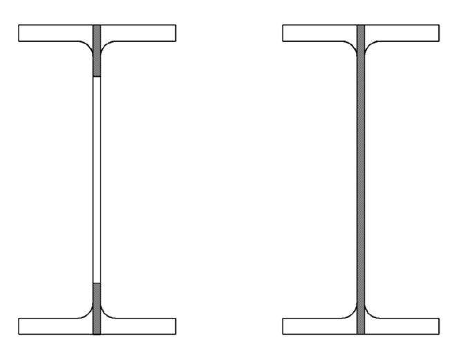
Gross and Net Area Shear Control
Shear control with the gross area is the full web part of the castellated beam, while the shear control with the net area is calculated by considering the castellated beam's hollow section.
'%3e%3cg transform='translate(167%2c0)'%3e%3cg transform='translate(-13%2c0)'%3e%3cg transform='translate(0%2c-3)'%3e%3cuse xlink:href='%23MJMATHI-56' x='0' y='0'%3e%3c/use%3e%3cuse transform='scale(0.707)' xlink:href='%23MJMATHI-6E' x='825' y='-213'%3e%3c/use%3e%3cuse xlink:href='%23MJMAIN-3D' x='1385' y='0'%3e%3c/use%3e%3cg transform='translate(2442%2c0)'%3e%3cuse xlink:href='%23MJMAIN-30'%3e%3c/use%3e%3cuse xlink:href='%23MJMAIN-2E' x='500' y='0'%3e%3c/use%3e%3cuse xlink:href='%23MJMAIN-36' x='779' y='0'%3e%3c/use%3e%3c/g%3e%3cg transform='translate(3721%2c0)'%3e%3cuse xlink:href='%23MJMATHI-46' x='0' y='0'%3e%3c/use%3e%3cuse transform='scale(0.707)' xlink:href='%23MJMATHI-79' x='910' y='-213'%3e%3c/use%3e%3c/g%3e%3cuse xlink:href='%23MJMATHI-62' x='4816' y='0'%3e%3c/use%3e%3cuse xlink:href='%23MJMATHI-74' x='5246' y='0'%3e%3c/use%3e%3cg transform='translate(5607%2c0)'%3e%3cuse xlink:href='%23MJMATHI-43' x='0' y='0'%3e%3c/use%3e%3cg transform='translate(715%2c-150)'%3e%3cuse transform='scale(0.707)' xlink:href='%23MJMATHI-76' x='0' y='0'%3e%3c/use%3e%3cuse transform='scale(0.707)' xlink:href='%23MJMAIN-32' x='485' y='0'%3e%3c/use%3e%3c/g%3e%3c/g%3e%3cuse xlink:href='%23MJMAIN-28' x='17120' y='0'%3e%3c/use%3e%3cuse xlink:href='%23MJMATHI-47' x='17510' y='0'%3e%3c/use%3e%3cuse xlink:href='%23MJMAIN-33' x='18296' y='0'%3e%3c/use%3e%3cuse xlink:href='%23MJMAIN-2212' x='19019' y='0'%3e%3c/use%3e%3cuse xlink:href='%23MJMAIN-31' x='20020' y='0'%3e%3c/use%3e%3cuse xlink:href='%23MJMAIN-29' x='20520' y='0'%3e%3c/use%3e%3c/g%3e%3c/g%3e%3c/g%3e%3c/g%3e%3c/svg%3e)
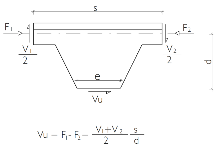
Horizontal Shear Control
The shear force on the castellated beam web is calculated using the balance equation and compared with the shear strength.
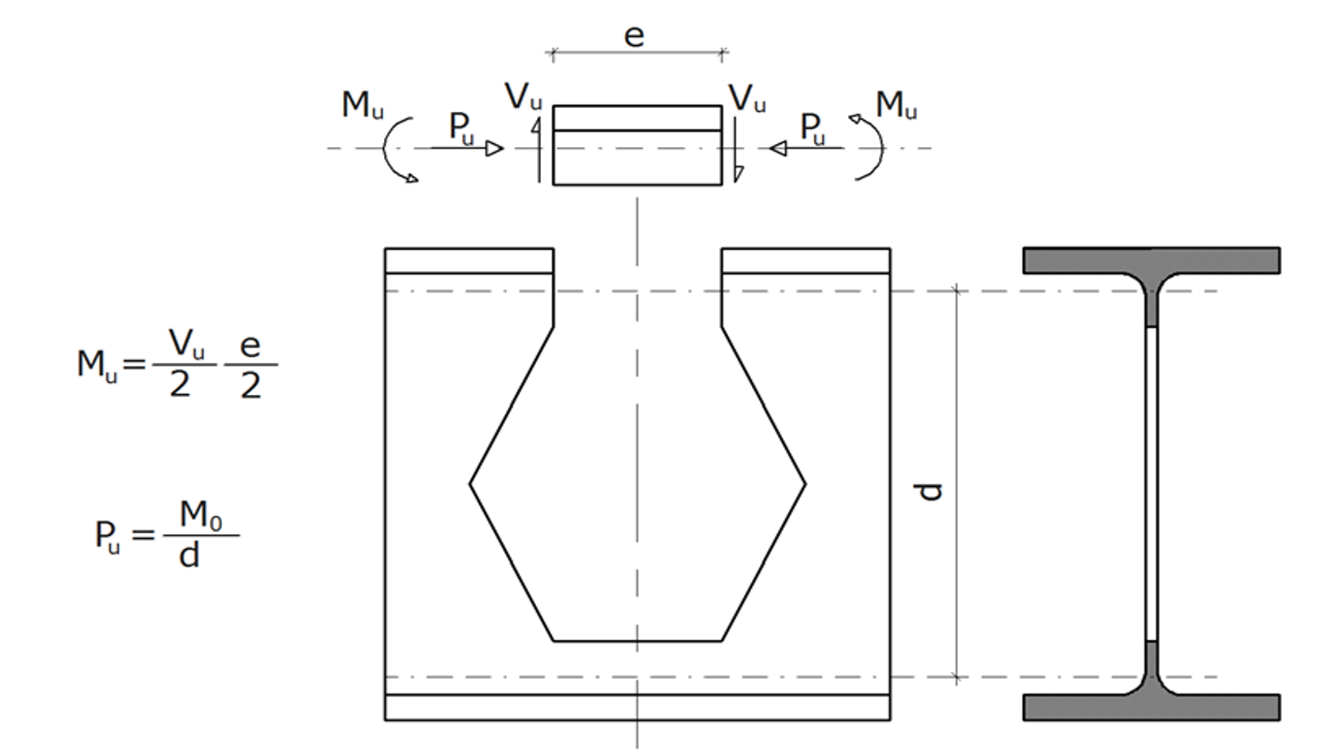
Vierendeel Bending Control
Axial Force and Biaxial Bending
The effects of the T section on the castellated beam spaces are found with the equilibrium equation. Internal force diagrams are used in the static analysis while calculating these forces. The equation of equilibrium calculates the bending moment and axial force on the T section. Then, the combined effects are considered by calculating the T-section bending and axial force strengths.
Web Post Buckling Control
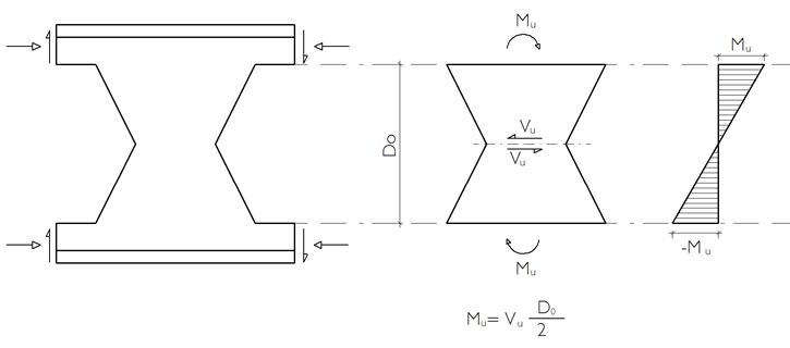
Forces Acting on the Web
The bending moment values at the upper and lower boundaries of the web section between the castellated beam spaces are found, and lateral-torsional buckling is checked according to the rectangular section.
Web Post Buckling Strength
The web section between the castellated beam is calculated according to AISC 360-16 Section F.
-
The limit state of flange local buckling does not apply to sections with compact flanges.
'%3e%3cg transform='translate(167%2c0)'%3e%3cg transform='translate(-13%2c0)'%3e%3cg transform='translate(0%2c-3)'%3e%3cuse xlink:href='%23MJMATHI-4D' x='0' y='0'%3e%3c/use%3e%3cuse transform='scale(0.707)' xlink:href='%23MJMATHI-6E' x='1372' y='-213'%3e%3c/use%3e%3cuse xlink:href='%23MJMAIN-3D' x='1772' y='0'%3e%3c/use%3e%3cg transform='translate(2829%2c0)'%3e%3cuse xlink:href='%23MJMATHI-4D' x='0' y='0'%3e%3c/use%3e%3cuse transform='scale(0.707)' xlink:href='%23MJMATHI-70' x='1372' y='-213'%3e%3c/use%3e%3c/g%3e%3cuse xlink:href='%23MJMAIN-3D' x='4533' y='0'%3e%3c/use%3e%3cg transform='translate(5589%2c0)'%3e%3cuse xlink:href='%23MJMATHI-46' x='0' y='0'%3e%3c/use%3e%3cuse transform='scale(0.707)' xlink:href='%23MJMATHI-79' x='910' y='-213'%3e%3c/use%3e%3c/g%3e%3cg transform='translate(6685%2c0)'%3e%3cuse xlink:href='%23MJMATHI-5A' x='0' y='0'%3e%3c/use%3e%3cuse transform='scale(0.707)' xlink:href='%23MJMATHI-79' x='966' y='-213'%3e%3c/use%3e%3c/g%3e%3cuse xlink:href='%23MJMAIN-2264' x='8098' y='0'%3e%3c/use%3e%3cg transform='translate(9154%2c0)'%3e%3cuse xlink:href='%23MJMAIN-31'%3e%3c/use%3e%3cuse xlink:href='%23MJMAIN-2E' x='500' y='0'%3e%3c/use%3e%3cuse xlink:href='%23MJMAIN-36' x='779' y='0'%3e%3c/use%3e%3c/g%3e%3cg transform='translate(10433%2c0)'%3e%3cuse xlink:href='%23MJMATHI-46' x='0' y='0'%3e%3c/use%3e%3cuse transform='scale(0.707)' xlink:href='%23MJMATHI-79' x='910' y='-213'%3e%3c/use%3e%3c/g%3e%3cg transform='translate(11529%2c0)'%3e%3cuse xlink:href='%23MJMATHI-53' x='0' y='0'%3e%3c/use%3e%3cuse transform='scale(0.707)' xlink:href='%23MJMATHI-79' x='867' y='-213'%3e%3c/use%3e%3c/g%3e%3cuse xlink:href='%23MJMAIN-28' x='22594' y='0'%3e%3c/use%3e%3cuse xlink:href='%23MJMATHI-46' x='22983' y='0'%3e%3c/use%3e%3cuse xlink:href='%23MJMAIN-36' x='23733' y='0'%3e%3c/use%3e%3cuse xlink:href='%23MJMAIN-2212' x='24456' y='0'%3e%3c/use%3e%3cuse xlink:href='%23MJMAIN-31' x='25456' y='0'%3e%3c/use%3e%3cuse xlink:href='%23MJMAIN-29' x='25957' y='0'%3e%3c/use%3e%3c/g%3e%3c/g%3e%3c/g%3e%3c/g%3e%3c/svg%3e)
-
The nominal flexural strength, Mn, is calculated below for sections with noncompact flanges.
'%3e%3cg transform='translate(167%2c0)'%3e%3cg transform='translate(-13%2c0)'%3e%3cuse xlink:href='%23MJMATHI-4D' x='0' y='0'%3e%3c/use%3e%3cuse transform='scale(0.707)' xlink:href='%23MJMATHI-6E' x='1372' y='-213'%3e%3c/use%3e%3cuse xlink:href='%23MJMAIN-3D' x='1772' y='0'%3e%3c/use%3e%3cg transform='translate(2829%2c0)'%3e%3cuse xlink:href='%23MJMATHI-4D' x='0' y='0'%3e%3c/use%3e%3cuse transform='scale(0.707)' xlink:href='%23MJMATHI-70' x='1372' y='-213'%3e%3c/use%3e%3c/g%3e%3cuse xlink:href='%23MJMAIN-2212' x='4477' y='0'%3e%3c/use%3e%3cuse xlink:href='%23MJMAIN-28' x='5478' y='0'%3e%3c/use%3e%3cg transform='translate(5868%2c0)'%3e%3cuse xlink:href='%23MJMATHI-4D' x='0' y='0'%3e%3c/use%3e%3cuse transform='scale(0.707)' xlink:href='%23MJMATHI-70' x='1372' y='-213'%3e%3c/use%3e%3c/g%3e%3cuse xlink:href='%23MJMAIN-2212' x='7516' y='0'%3e%3c/use%3e%3cg transform='translate(8517%2c0)'%3e%3cuse xlink:href='%23MJMAIN-30'%3e%3c/use%3e%3cuse xlink:href='%23MJMAIN-2E' x='500' y='0'%3e%3c/use%3e%3cuse xlink:href='%23MJMAIN-37' x='779' y='0'%3e%3c/use%3e%3c/g%3e%3cg transform='translate(9797%2c0)'%3e%3cuse xlink:href='%23MJMATHI-46' x='0' y='0'%3e%3c/use%3e%3cuse transform='scale(0.707)' xlink:href='%23MJMATHI-79' x='910' y='-213'%3e%3c/use%3e%3c/g%3e%3cg transform='translate(10892%2c0)'%3e%3cuse xlink:href='%23MJMATHI-53' x='0' y='0'%3e%3c/use%3e%3cuse transform='scale(0.707)' xlink:href='%23MJMATHI-79' x='867' y='-213'%3e%3c/use%3e%3c/g%3e%3cuse xlink:href='%23MJMAIN-29' x='11957' y='0'%3e%3c/use%3e%3cuse xlink:href='%23MJSZ3-28' x='12347' y='-1'%3e%3c/use%3e%3cg transform='translate(13083%2c0)'%3e%3cg transform='translate(120%2c0)'%3e%3crect stroke='none' width='4163' height='60' x='0' y='220'%3e%3c/rect%3e%3cg transform='translate(464%2c794)'%3e%3cuse xlink:href='%23MJMATHI-3BB' x='0' y='0'%3e%3c/use%3e%3cuse xlink:href='%23MJMAIN-2212' x='805' y='0'%3e%3c/use%3e%3cg transform='translate(1806%2c0)'%3e%3cuse xlink:href='%23MJMATHI-3BB' x='0' y='0'%3e%3c/use%3e%3cg transform='translate(583%2c-155)'%3e%3cuse transform='scale(0.707)' xlink:href='%23MJMATHI-70' x='0' y='0'%3e%3c/use%3e%3cuse transform='scale(0.707)' xlink:href='%23MJMATHI-66' x='503' y='0'%3e%3c/use%3e%3c/g%3e%3c/g%3e%3c/g%3e%3cg transform='translate(60%2c-689)'%3e%3cuse xlink:href='%23MJMATHI-3BB' x='0' y='0'%3e%3c/use%3e%3cg transform='translate(583%2c-155)'%3e%3cuse transform='scale(0.707)' xlink:href='%23MJMATHI-72' x='0' y='0'%3e%3c/use%3e%3cuse transform='scale(0.707)' xlink:href='%23MJMATHI-66' x='451' y='0'%3e%3c/use%3e%3c/g%3e%3cuse xlink:href='%23MJMAIN-2212' x='1614' y='0'%3e%3c/use%3e%3cg transform='translate(2614%2c0)'%3e%3cuse xlink:href='%23MJMATHI-3BB' x='0' y='0'%3e%3c/use%3e%3cg transform='translate(583%2c-155)'%3e%3cuse transform='scale(0.707)' xlink:href='%23MJMATHI-70' x='0' y='0'%3e%3c/use%3e%3cuse transform='scale(0.707)' xlink:href='%23MJMATHI-66' x='503' y='0'%3e%3c/use%3e%3c/g%3e%3c/g%3e%3c/g%3e%3c/g%3e%3c/g%3e%3cuse xlink:href='%23MJSZ3-29' x='17487' y='-1'%3e%3c/use%3e%3cuse xlink:href='%23MJMAIN-28' x='28223' y='0'%3e%3c/use%3e%3cuse xlink:href='%23MJMATHI-46' x='28613' y='0'%3e%3c/use%3e%3cuse xlink:href='%23MJMAIN-36' x='29362' y='0'%3e%3c/use%3e%3cuse xlink:href='%23MJMAIN-2212' x='30085' y='0'%3e%3c/use%3e%3cuse xlink:href='%23MJMAIN-32' x='31086' y='0'%3e%3c/use%3e%3cuse xlink:href='%23MJMAIN-29' x='31586' y='0'%3e%3c/use%3e%3c/g%3e%3c/g%3e%3c/g%3e%3c/svg%3e)
-
The nominal flexural strength, Mn, is calculated below for sections with slender flanges.
'%3e%3cg transform='translate(167%2c0)'%3e%3cg transform='translate(-13%2c0)'%3e%3cg transform='translate(0%2c-3)'%3e%3cuse xlink:href='%23MJMATHI-4D' x='0' y='0'%3e%3c/use%3e%3cuse transform='scale(0.707)' xlink:href='%23MJMATHI-6E' x='1372' y='-213'%3e%3c/use%3e%3cuse xlink:href='%23MJMAIN-3D' x='1772' y='0'%3e%3c/use%3e%3cg transform='translate(2829%2c0)'%3e%3cuse xlink:href='%23MJMATHI-46' x='0' y='0'%3e%3c/use%3e%3cg transform='translate(643%2c-150)'%3e%3cuse transform='scale(0.707)' xlink:href='%23MJMATHI-63' x='0' y='0'%3e%3c/use%3e%3cuse transform='scale(0.707)' xlink:href='%23MJMATHI-72' x='433' y='0'%3e%3c/use%3e%3c/g%3e%3c/g%3e%3cg transform='translate(4198%2c0)'%3e%3cuse xlink:href='%23MJMATHI-53' x='0' y='0'%3e%3c/use%3e%3cuse transform='scale(0.707)' xlink:href='%23MJMATHI-79' x='867' y='-213'%3e%3c/use%3e%3c/g%3e%3cuse xlink:href='%23MJMAIN-28' x='15263' y='0'%3e%3c/use%3e%3cuse xlink:href='%23MJMATHI-46' x='15653' y='0'%3e%3c/use%3e%3cuse xlink:href='%23MJMAIN-36' x='16402' y='0'%3e%3c/use%3e%3cuse xlink:href='%23MJMAIN-2212' x='17125' y='0'%3e%3c/use%3e%3cuse xlink:href='%23MJMAIN-33' x='18126' y='0'%3e%3c/use%3e%3cuse xlink:href='%23MJMAIN-29' x='18626' y='0'%3e%3c/use%3e%3c/g%3e%3c/g%3e%3c/g%3e%3c/g%3e%3c/svg%3e)
'%3e%3cg transform='translate(167%2c0)'%3e%3cg transform='translate(-13%2c0)'%3e%3cg transform='translate(0%2c747)'%3e%3cuse xlink:href='%23MJMATHI-46' x='0' y='0'%3e%3c/use%3e%3cg transform='translate(643%2c-150)'%3e%3cuse transform='scale(0.707)' xlink:href='%23MJMATHI-63' x='0' y='0'%3e%3c/use%3e%3cuse transform='scale(0.707)' xlink:href='%23MJMATHI-72' x='433' y='0'%3e%3c/use%3e%3c/g%3e%3cuse xlink:href='%23MJMAIN-3D' x='1647' y='0'%3e%3c/use%3e%3cg transform='translate(2703%2c0)'%3e%3cg transform='translate(120%2c0)'%3e%3crect stroke='none' width='2979' height='60' x='0' y='220'%3e%3c/rect%3e%3cg transform='translate(217%2c676)'%3e%3cuse xlink:href='%23MJMAIN-30'%3e%3c/use%3e%3cuse xlink:href='%23MJMAIN-2E' x='500' y='0'%3e%3c/use%3e%3cuse xlink:href='%23MJMAIN-36' x='779' y='0'%3e%3c/use%3e%3cuse xlink:href='%23MJMAIN-39' x='1279' y='0'%3e%3c/use%3e%3cuse xlink:href='%23MJMATHI-45' x='1780' y='0'%3e%3c/use%3e%3c/g%3e%3cg transform='translate(60%2c-1366)'%3e%3cuse xlink:href='%23MJSZ2-28' x='0' y='-1'%3e%3c/use%3e%3cg transform='translate(597%2c0)'%3e%3cg transform='translate(120%2c0)'%3e%3crect stroke='none' width='970' height='60' x='0' y='220'%3e%3c/rect%3e%3cuse xlink:href='%23MJMATHI-62' x='270' y='676'%3e%3c/use%3e%3cg transform='translate(60%2c-686)'%3e%3cuse xlink:href='%23MJMATHI-74' x='0' y='0'%3e%3c/use%3e%3cuse transform='scale(0.707)' xlink:href='%23MJMATHI-66' x='511' y='-219'%3e%3c/use%3e%3c/g%3e%3c/g%3e%3c/g%3e%3cg transform='translate(1808%2c0)'%3e%3cuse xlink:href='%23MJSZ2-29' x='0' y='-1'%3e%3c/use%3e%3cuse transform='scale(0.707)' xlink:href='%23MJMAIN-32' x='844' y='1240'%3e%3c/use%3e%3c/g%3e%3c/g%3e%3c/g%3e%3c/g%3e%3cuse xlink:href='%23MJMAIN-28' x='15923' y='0'%3e%3c/use%3e%3cuse xlink:href='%23MJMATHI-46' x='16312' y='0'%3e%3c/use%3e%3cuse xlink:href='%23MJMAIN-36' x='17062' y='0'%3e%3c/use%3e%3cuse xlink:href='%23MJMAIN-2212' x='17784' y='0'%3e%3c/use%3e%3cuse xlink:href='%23MJMAIN-34' x='18785' y='0'%3e%3c/use%3e%3cuse xlink:href='%23MJMAIN-29' x='19285' y='0'%3e%3c/use%3e%3c/g%3e%3c/g%3e%3c/g%3e%3c/g%3e%3c/svg%3e)
Next Topic