
The physical model created in the interface during the building modeling is converted into an analytical model according to the finite element method. In the analytical model, steel elements are modeled as bar elements according to the finite element method. Different analysis model conditions are created according to the combination types used in this modeling and optionally defined degrees of freedom.
The degrees of freedom in steel elements are directly related to the defined connections. According to the type of connection to be defined, the behavior of rigid connections, hinged connections and semi-rigid connections is reflected in the analysis model.
There are 6 degrees of freedom in a cross-section of a bar element for which three-dimensional analysis is performed. These are translations in directions 1,2 and 3 and rotations about 1,2 and 3.
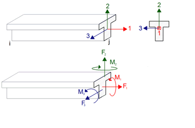
Direction 1 - Red indicates the axial force of the element in the direction of its axis. The force shown in the 1 axis direction is taken into account as the positive direction. It also means that the force in the extension direction of the rod is also positive.
Direction 1 - Red represents the rotation around the torsional moment of the element. The freedom of rotation around the 1 axis shown in the picture above is taken into account as the positive direction. Torsional moment of the element as shown in the picture above, when viewed from the cross section, is positive if counterclockwise, and negative if clockwise.
Direction 2 - Green, the force in the direction of its axis is expressed as the shear force. The translational freedom indicated by the 2 axis is taken into account as the positive direction. This is also the shear force value in the major direction of the element. If the internal force vector in the cross section of the bar element is in the direction of the 2 axis as shown in the picture above, the shear force is positive, and if it is in the opposite direction of the 2 axis, the shear force is negative.
Direction 2 - Green, the shape indicated by the freedom of rotation about its axis is considered as the bending moment. The freedom of rotation around the 2 axis shown in the picture above is considered as the positive direction. When the element section is viewed from the opposite side as shown in the figure, if the moment about the 2 axis is positive, pressure on the left side of the section and tensile stress on the right side of the section.
Direction 3 - Blue, the force in the direction of its axis is expressed as the shear force. The translational freedom indicated by the 3 axis is taken into account as the positive direction. If the vector of the shear force is in the 3 axis direction shown in the picture above, it takes a positive value, and if it is in the opposite direction of the 3 axis, it takes a negative value.
Direction 3 - Blue, the rotational freedom around its axis is taken into account as the bending moment. The freedom of rotation around the 3 axis shown in the picture above is taken into account as the positive direction. The bending moment about the 3 axis is also called the bending moment in the major direction or the strong axis.
The combinations defined in the steel elements cause changes in the degrees of freedom described above. These changes should be reflected in the analysis model appropriately, and internal forces and then the element design should be made appropriately.
Connection types according to degrees of freedom are defined below, respectively.
Rigid Connection
The rigid connection creates rigidity and receives internal force for all 6 degrees of release created without defining any support conditions of the steel members.
In order for a rigid connection to be applied in any steel element, it is sufficient to keep the end releases closed.
Articulated Connection (Release of Rotation)
Articulated connection is a type of connection in which the steel elements connected to each other are free to rotate and as a result of this, no moment occurs at the element end. If any slip connection (hinged connection) is defined at the steel element end, release is defined for the M2 and M3 moments with respect to the local axes of the bar element. In this case, as a result of the analysis made, the M3 and M2 moments will be zero at the end forces of the bar to which the hinged connection is made.
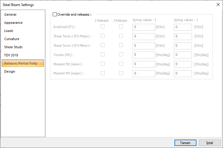
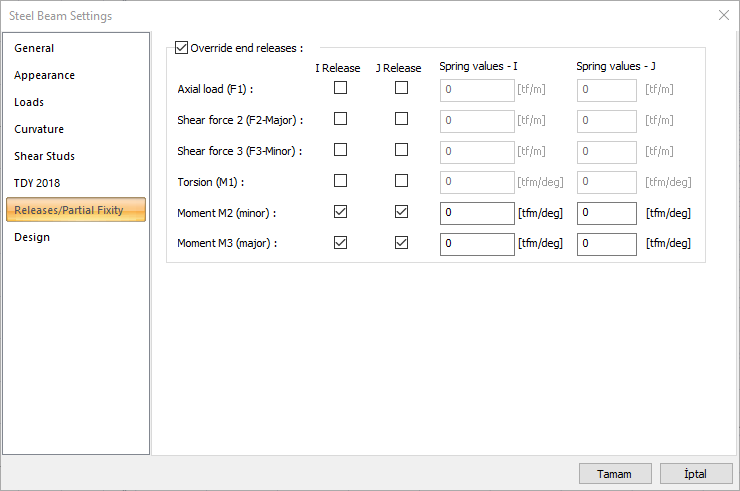
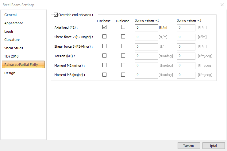
If it is intended to define an articulated connection for the i and j ends of any steel element, the M2 and M3 boxes at the relevant ends are checked in the Releases/Partial Fixity tab of the steel element properties and the arc values are entered as “0” zero.
NOTE: If a slip connection is defined on the steel element, ideCAD automatically defines the structural articulated connection and creates the analysis model.
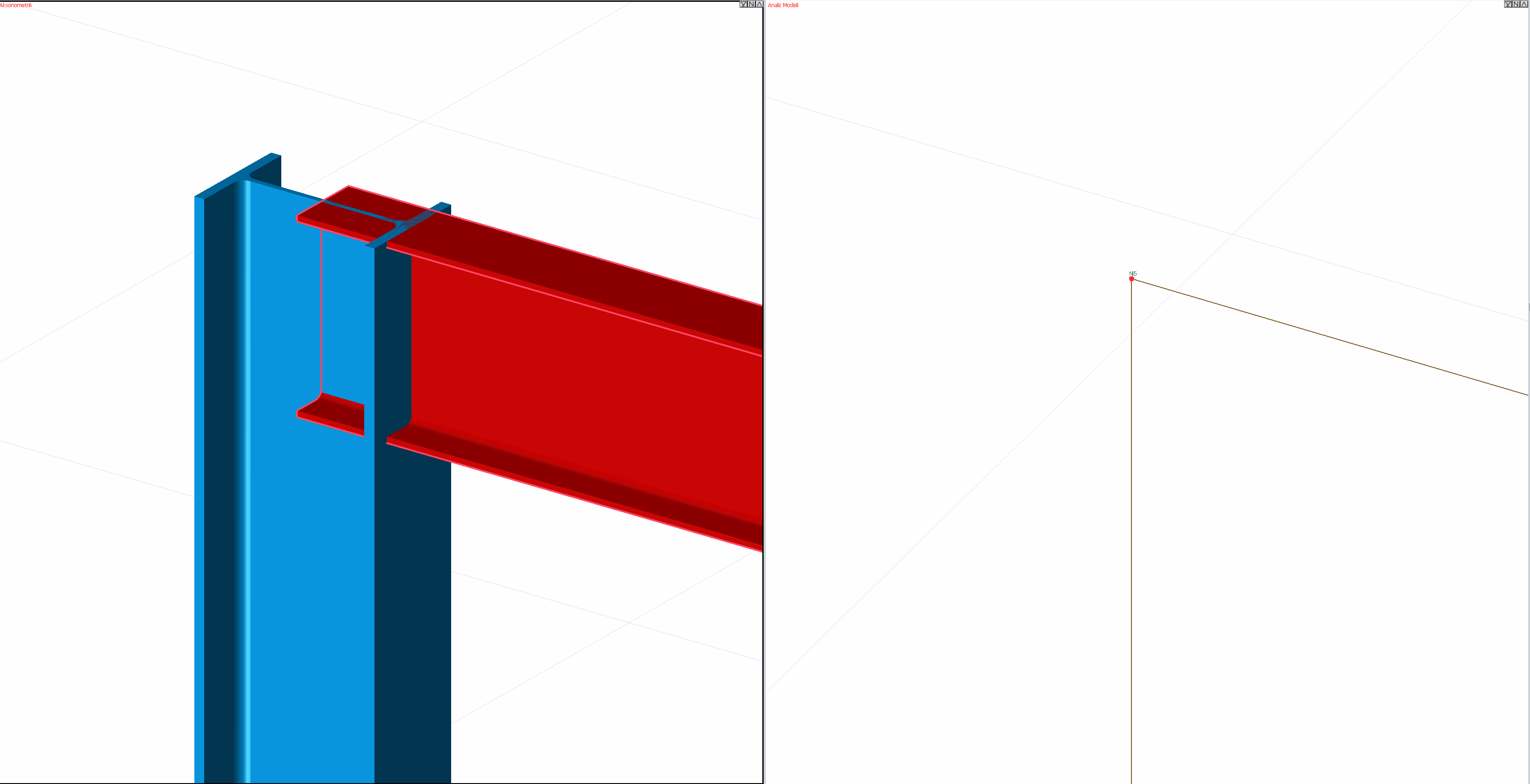
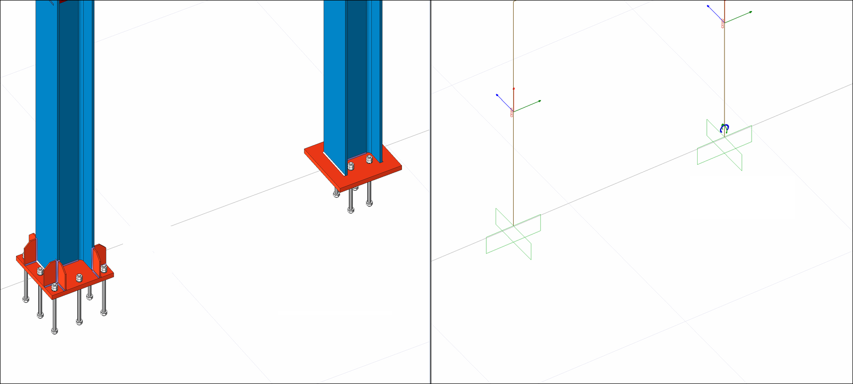
Examples of rigid and articulated pillar pillars for pillar connection are shown with the analysis model.
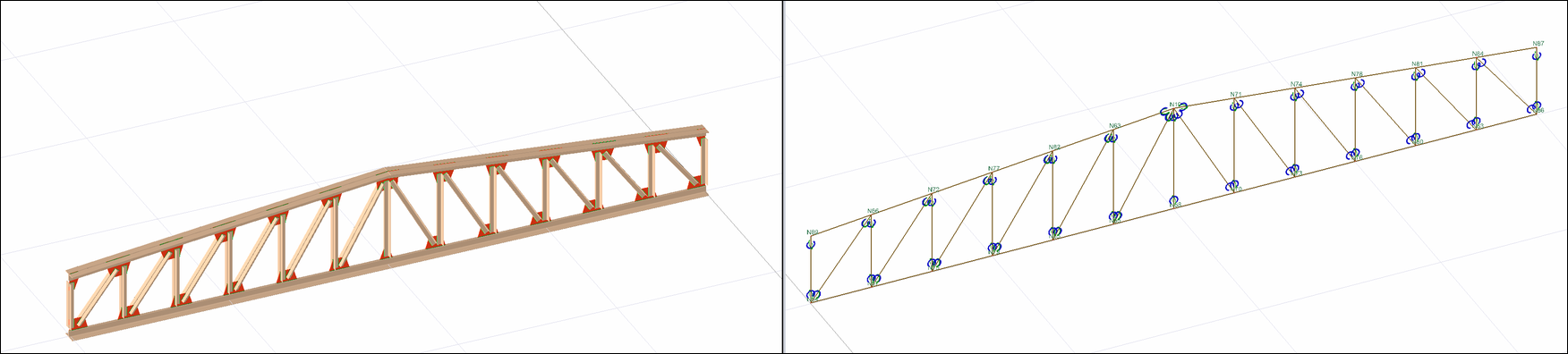
Articulated connections and analysis model defined for truss elements are shown in the picture below.
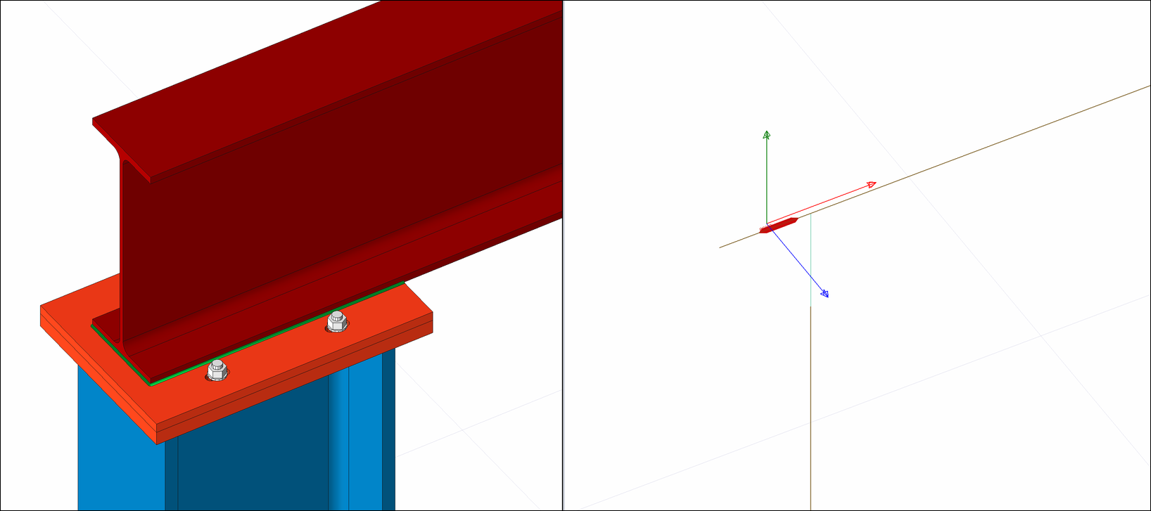
Release of translation
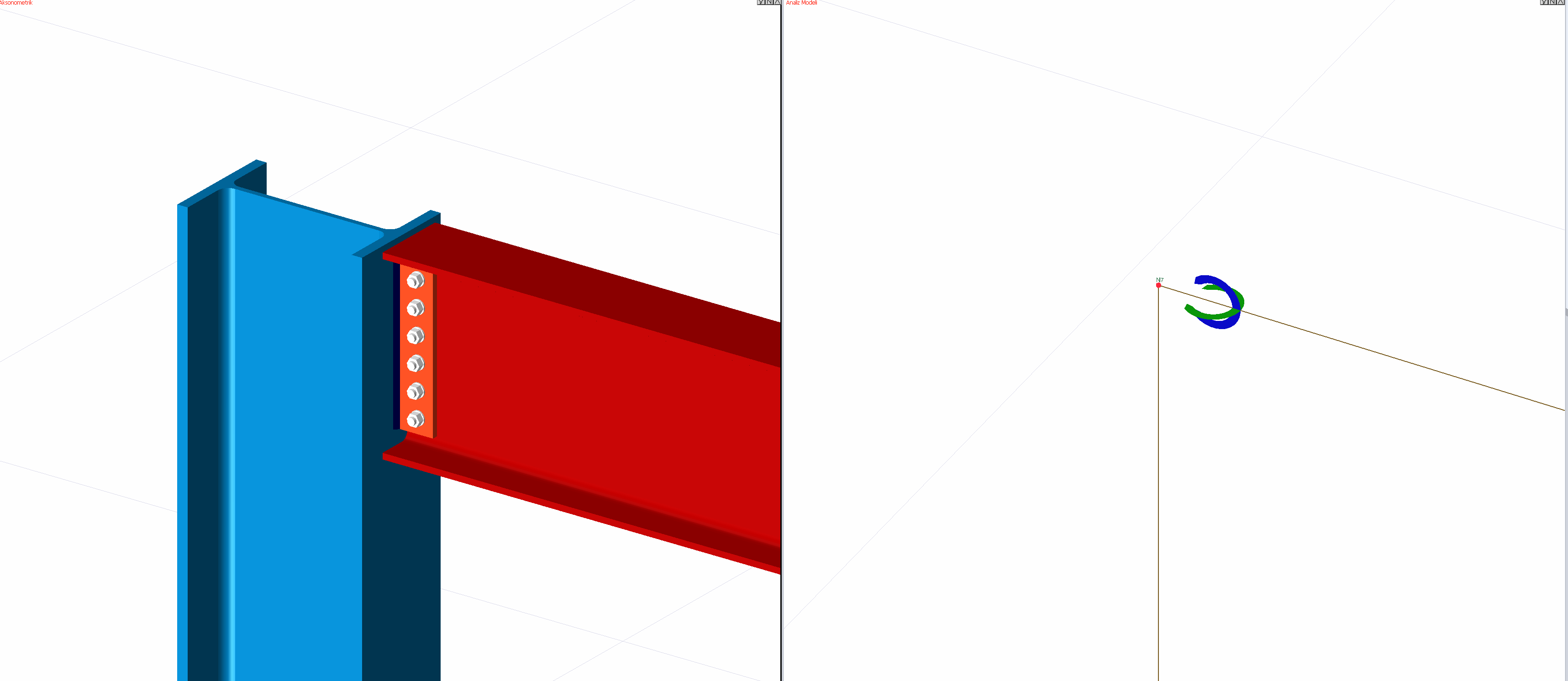
The translational release is the release of the axial load and shear forces. For the connection shown in the picture below, axial translation release will be given for the beam, since the holes are drilled to allow it to move in the plane perpendicular to the beam.
In order to create this situation in the analysis model, it is necessary to mark the F1 release at the relevant end from the releases tab of the steel element properties and enter the arc value as “0” zero.
Next Topic
Related Topics