
Symbols
D = Overstrength factor
fck = Specified compressive strength of concrete
fyk = Specified yield strength of the longitudinal reinforcement
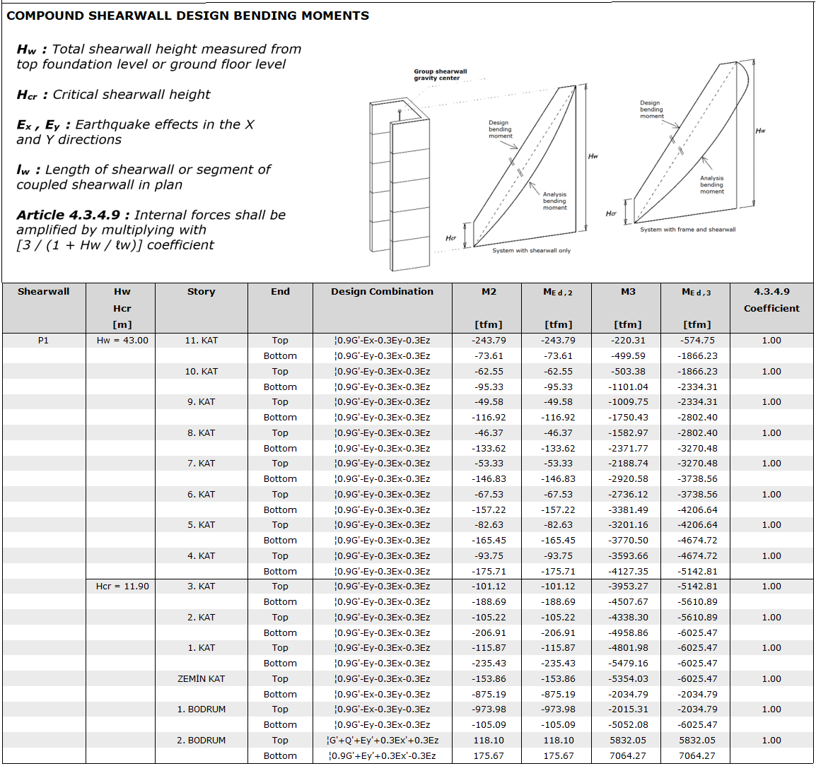
Hw = Total wall height measured from the top of the foundation or the ground floor slab
Hcr = Shearwall critical section height
lw = Shearwall or coupling-beam shearwall part length in plan
(Mp)t = probable flexural strength of members, with or without axial load, determined using the properties of the member at joint faces assuming tensile stress in the longitudinal bars of fyk and concrete compression stress fck
(Md)t = The moment calculated under the combined effect of the vertical loads and earthquake loads multiplied by the load coefficients in the base section of the shearwall
R = Response modification coefficient
Vd = The vertical loads and earthquake loads multiplied by the load coefficients Shear force calculated under the joint effect
Ve = design shear force for load combinations, including earthquake effects
βv = Shear force dynamic magnification coefficient at shearwall
Ach = Gross cross-section area of the wall without a gap, each shearwall piece in a coupling-beam shearwall, slab or each story piece in a hollow story
fctd = Design tensile strength of concrete
fywd = Design yield strength of the transverse reinforcement
Vr = Shear strength of column, beam, or shearwall section
ρsh = Volumetric ratio of horizontal web reinforcements in the shearwall
-
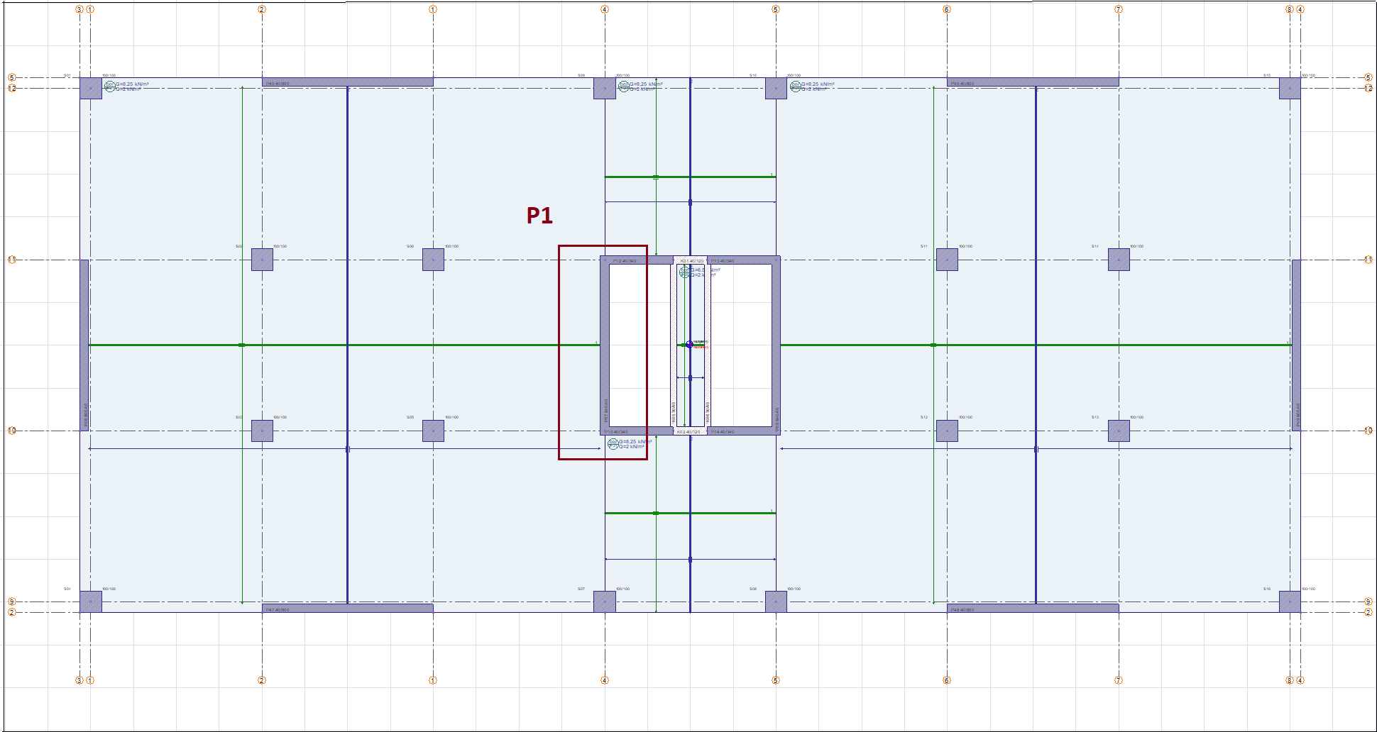
As an example, the design of the U-shaped shearwall group, which is the core shearwall named P1 on the ground story (first story above the basement) of the building, will be examined.
Shearwall Axial Force Control
-
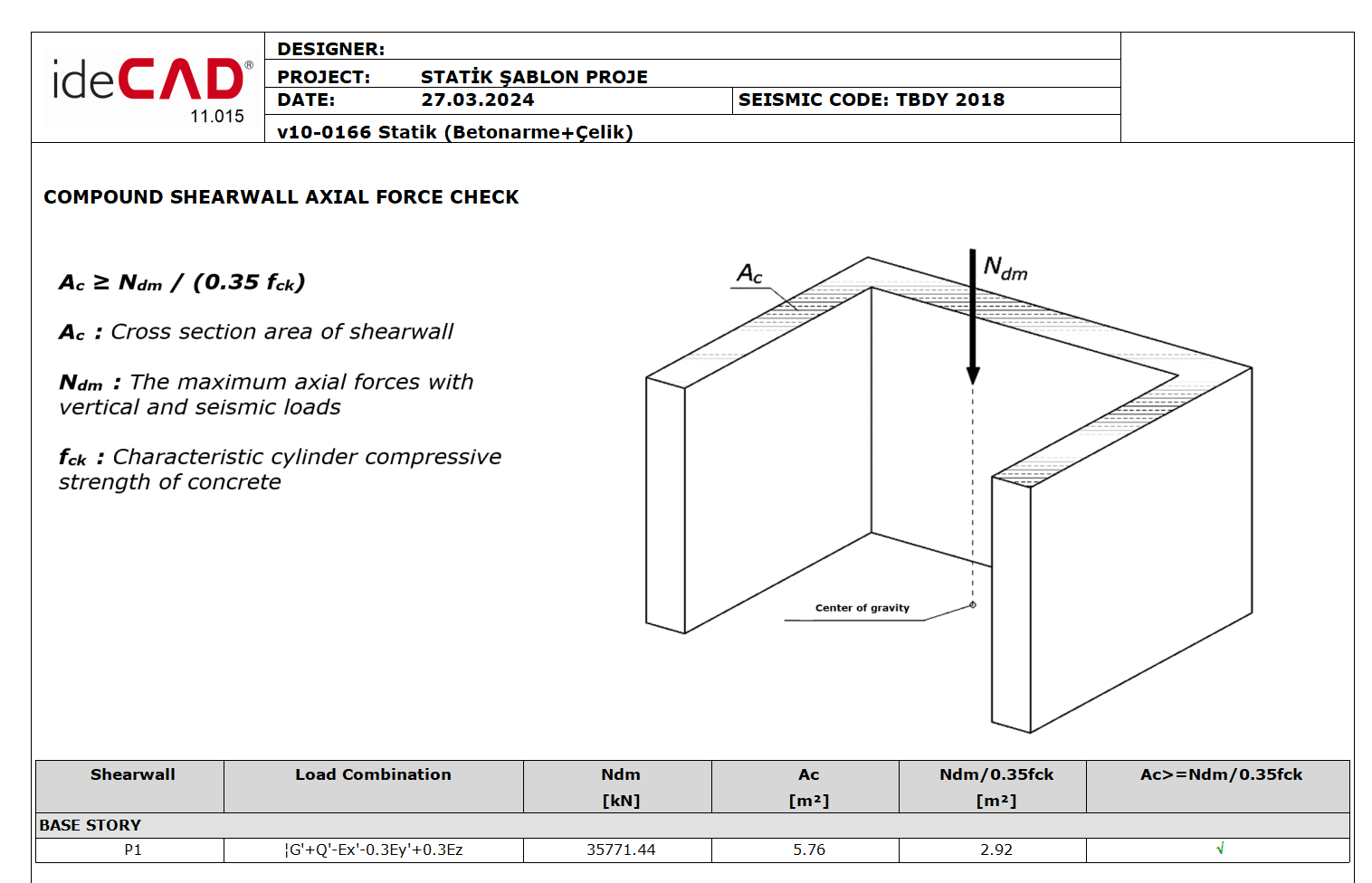
According to TBDY 7.6.1.1, the net area of the wall after the voids are removed, taking into consideration the live load reduction factor defined in Ndm TS 498, is the result of the axial compressive forces calculated in the case of G+Q+E loading under the joint effect of G and Q vertical loads and E earthquake effect must satisfy the Ac≥Ndm/(0.35fck) condition using the largest. In the calculation of Ac and Ndm values shearwalls, the entire section of the shearwall (sum of the wall parts) is taken into consideration.
-
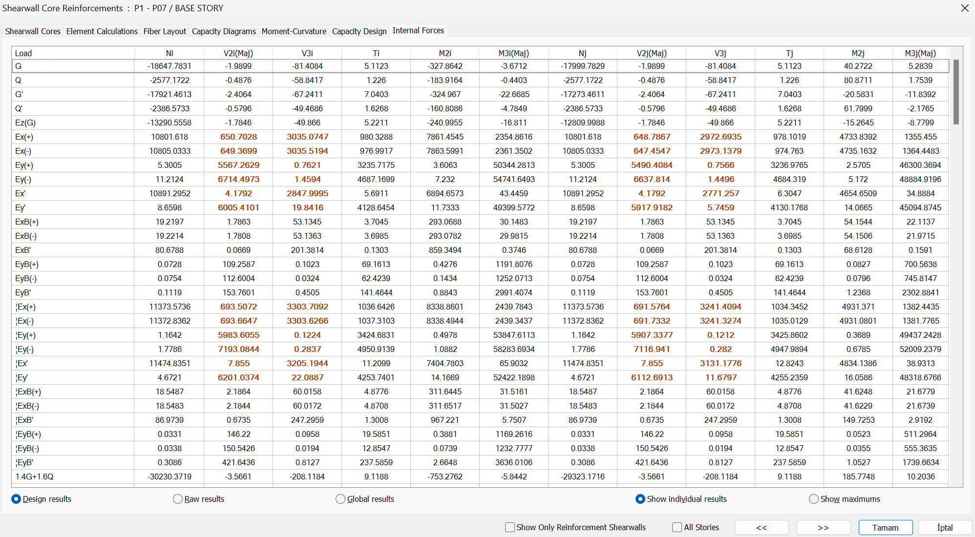
In the program, in the reinforced concrete design - wall group tab, all load combinations for the ground story P01 shearwalls are examined in the forces boundary, and the relevant loading and axial compression force for the case of G+Q+E, the largest axial compression force, are determined.
-
We can check whether the forces we get from the program meet the conditions as follows.
-
TBDY 7.6.1.1 control is summarized below in the shearwall group report obtained from the program.
-
It can be seen that the calculated values are compatible with the report.
Detection of Wall Cross and Longitudinal Reinforcements
-
In accordance with TBDY 7.6, the minimum longitudinal reinforcement and transverse reinforcement of the wall element that we consider as an example will be determined first. The element strengths obtained with these reinforcements will be compared with the design forces obtained from the calculation. If the strength values are smaller than the design forces, the required reinforcement will be revised and the required element strength will be obtained.
-
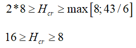
TBDY 7.6.2.2 must top foundation or the length of the wall plan from the level where more smaller than 20% of the critical wall height, 2lw to exceed the value is determined such that the more unfavorable in the following conditions.
-
If the first three stories above the ground story are determined as the critical shearwall height; Hcr = 11.5 m. ideCAD Structural determined the critical wall height from the ground as 11.9 m. Both values are compatible with each other.
Shearwall boundary Longitudinal and Transverse Reinforcement Calculation
-
Since the shearwall to be designed is on the first story on the ground, it is a shearwall located at the critical shearwall height. The plan length of each of the end zones along the critical wall height cannot be less than 20% of the total plan length of the wall and twice the thickness of the wall. (TBDY 7.6.2.3)
-
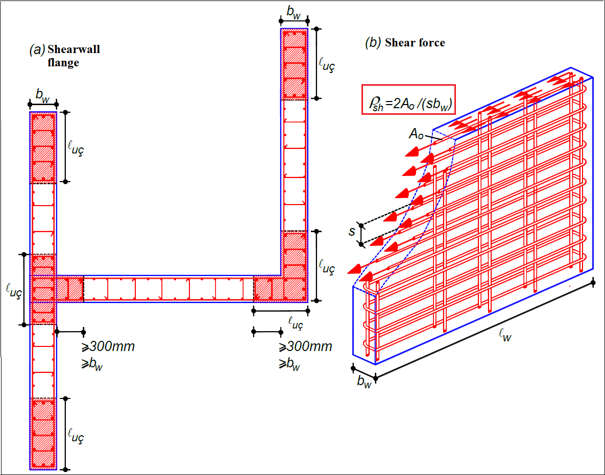
The ratio of the total vertical sonata area in each of the wall end zones along the critical wall height shall be at least 0.002, and at least 2/3 of the transverse reinforcement determined by the following condition for the confinement zones of the columns will be placed in the wall end regions. (TBDY 7.6.5.1 -7.6.5.2b)
Shearwall Web Longitudinal and Transverse Reinforcement Calculation
-
According to TBDY 7.6.2.3, the total cross-sectional area of the web reinforcements on both sides of the wall, for each longitudinal and transverse reinforcement, can not be less than 0.0025 of the gross cross-section area of the shearwall web remaining between the wall end regions.
-
According to the above information, projected wall boundary length, web longitudinal reinforcement diameter and spacing, web transverse reinforcement diameter and spacing, and web vertical reinforcement diameter and spacing are as follows.
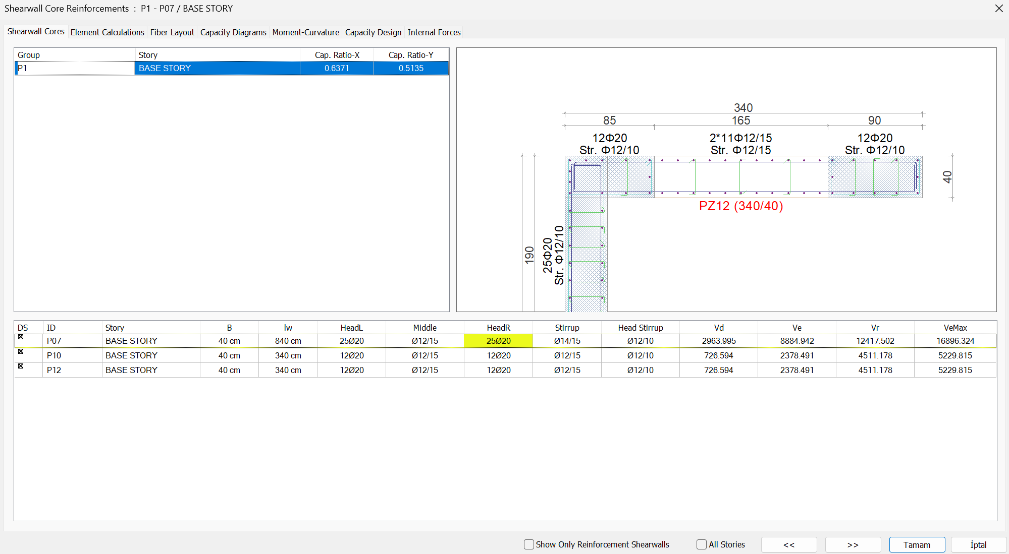
-
In the ideCAD Structural interface, the group wall reinforcement placement, and the lengths of the zone can be controlled, and the new reinforcement placement can be followed simultaneously by intervening in the reinforcement from this interface.
-
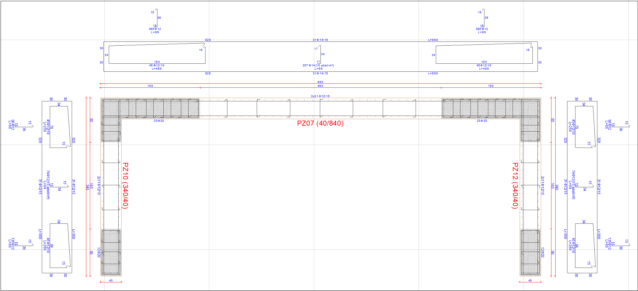
All reinforcements are summarized in the group wall drawing details below.
Shearwall Group Longitudinal Reinforcement Control
-
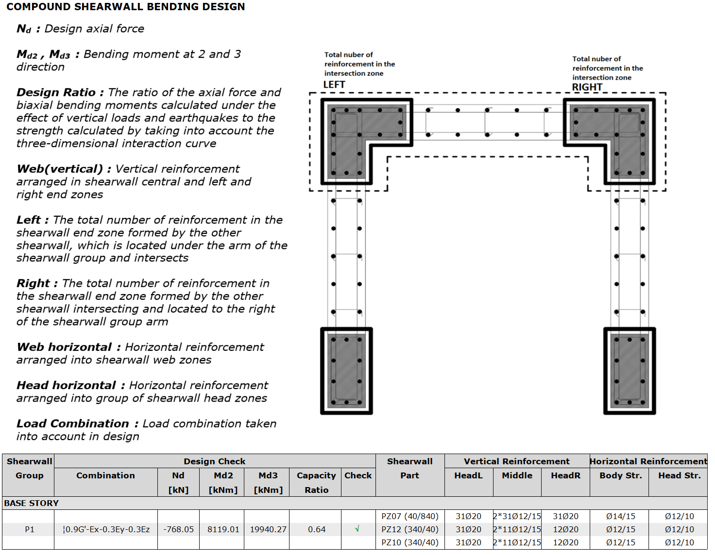
M2-M3 interaction diagram is obtained for axial force obtained for each load combination under the joint effect of vertical and seismic loads in the design on the yield surface created for the longitudinal reinforcements of the proposed wall group. It is checked whether the moment values obtained at the lower and upper ends of the shearwall group remain within this diagram. The amount of wall boundary and web longitudinal reinforcement stipulated in TBDY 2018 7.6.3 and 7.6.5 provides the design values obtained from the calculations.
-
Below are the results of the capacity diagrams section obtained from the program.
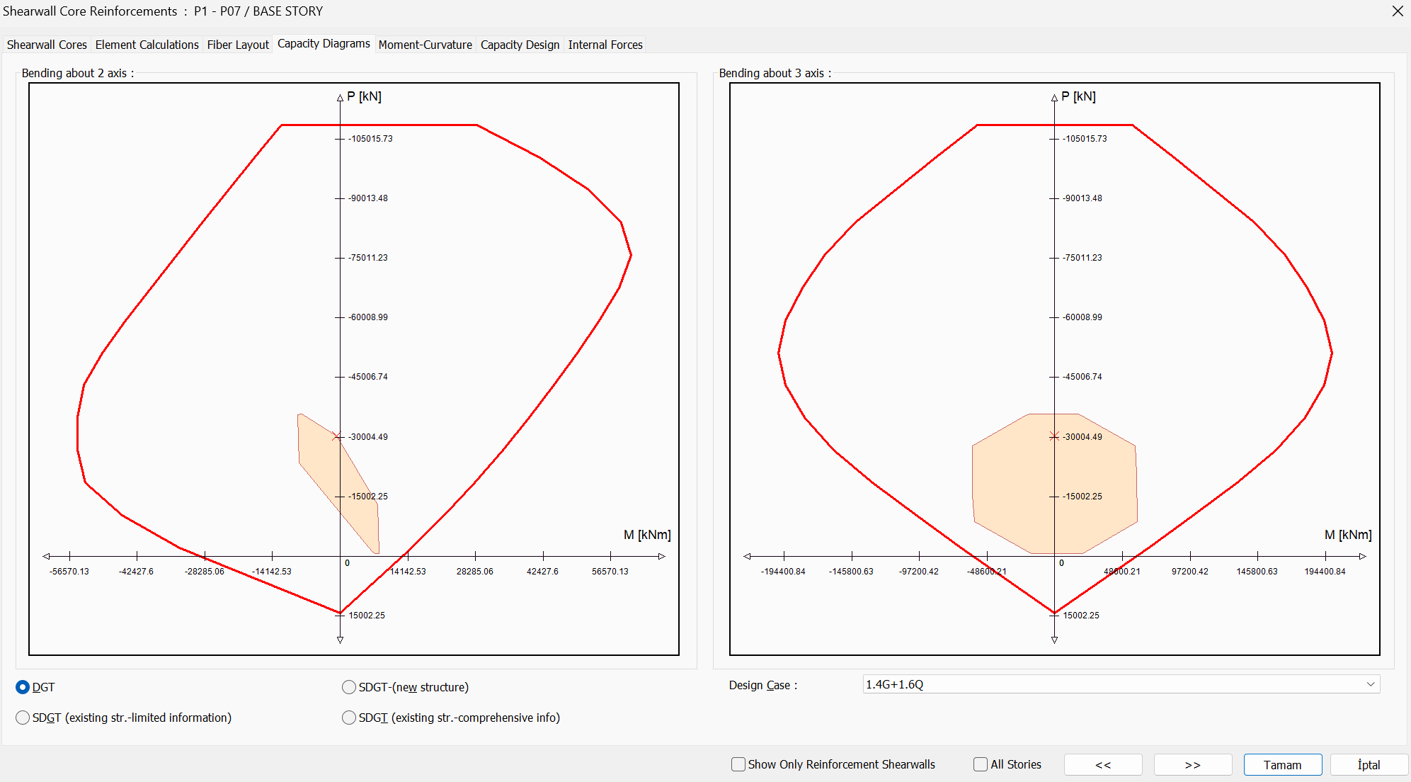
-
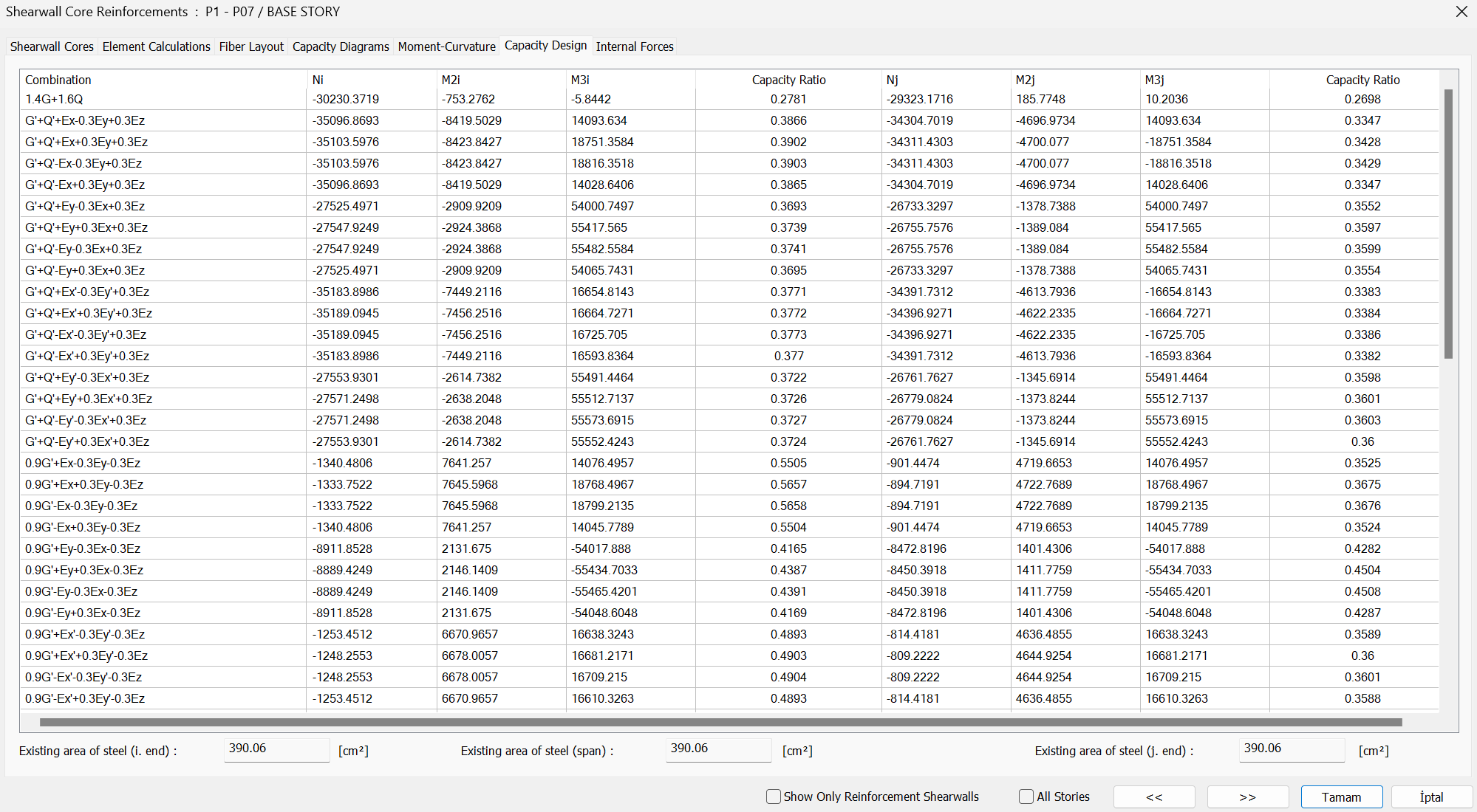
P-M2-M3 diagrams can be checked under all load combinations on the program interface. The moment values obtained at the upper and lower ends of the shearwall remain in the diagram. In the capacity design tab, the ratio can be controlled.
-
Group shearwall design bending moments calculation is reported as follows:
-
In the group shearwall report, reinforcement areas are given together with the relevant forces in the reinforced concrete account section.
Group Shearwall Design Bending Moment and Shear Force
-
According to TBDY 7.6.6.1, the design bending moments for walls meeting the Hw / lw> 2.0 condition are taken as a constant value along the critical wall height, equal to the bending moment calculated at the wall base. Above the section where the critical wall height ends, a linear moment diagram parallel to the line joining the moments calculated at the base and upper end of the wall is applied.
-
According to TBDY 7.6.6.3, the design shear force, Ve , to be taken as basis in calculating the transverse reinforcement in any section taken into consideration for walls meeting the Hw / lw> 2.0 condition , is calculated by Equation 7.16.
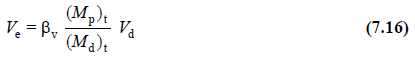
-
In the calculation, alınır v = 1.0 is taken as all of the earthquake load is covered by reinforced concrete walls in accordance with the analysis rules of the carrier system, including non-beam slab. If the value obtained by increasing the shear force calculated from the earthquake with vertical loads by 1.2D (gapless walls) or 1.4D (hollow walls) is less than V e calculated by equation 7.16, this shear force is used instead of Ve.
-
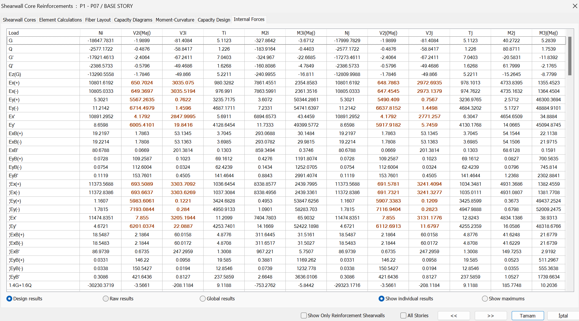
Vd and (Md)t values shown in TBDY Equation 7.16 are the values of shear force and bending moment calculated under the joint effect of vertical loads and seismic loads multiplied by load coefficients, respectively. In the group shearwall design, the bending moment is calculated at the center of gravity of the wall group, while the shear force is calculated separately for each shearwall arm at their center of gravity. For this reason, the Reinforced Concrete design - group shear dialog can be used for bending moment results, and the values read for G, Q, and Ey loads from the internal forces tab are substituted in the relevant combinations, and the result given in the report as below is reached. However, the results of all load conditions should be read separately for each arm from the perspective screen - analysis display - shearwall results section for shear force.
-
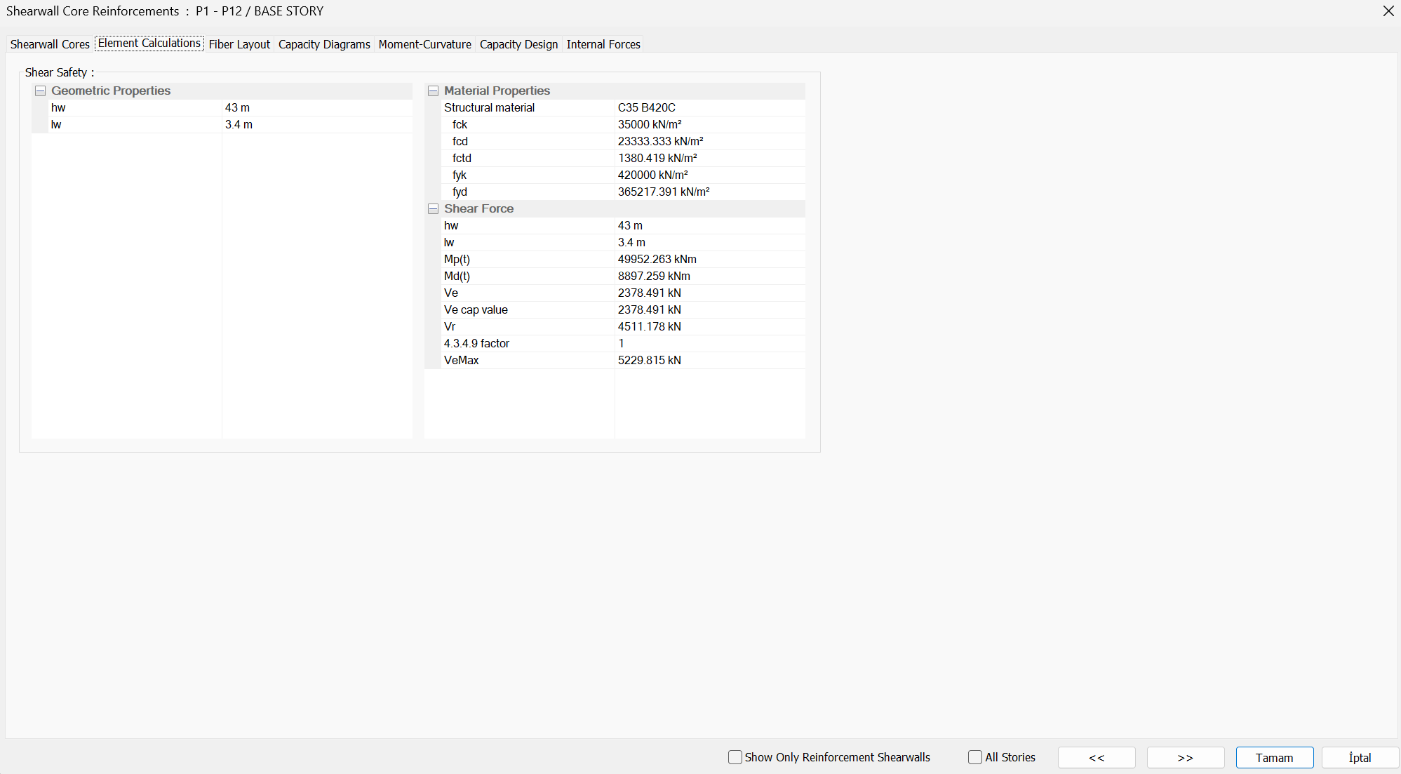
In this case Vd and (Md )t for the loading combination V d = 726.59 kN (Md)t =49952.26 kNm.
-
As a result of the moment-curvature analysis made by taking into consideration the axial force and biaxial bending under the load combination, in the calculation made by taking βv=1.0, the bearing found by using fck and fyk material strengths in the base section of the P1 group shear wall. The plastic bending moment capacity (Mp)t = 8897.26 kNm was found. In this case, the value of Ve' is found by Equation 7.16;
calculated as.
-
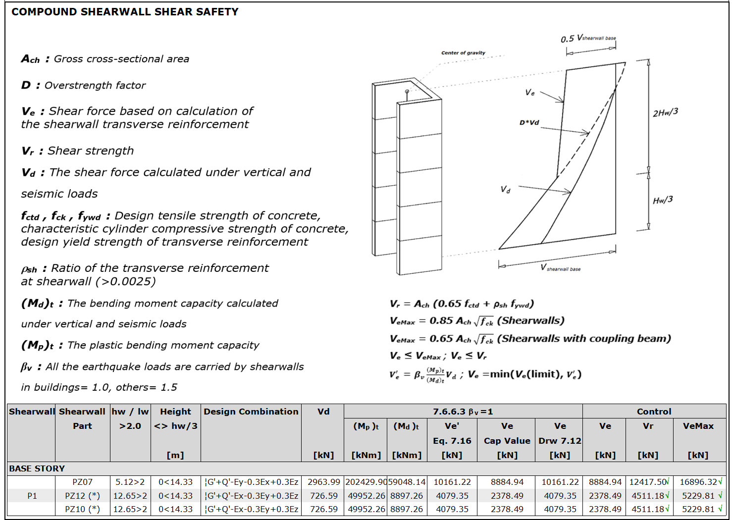
According to TBDY Article 7.6.6.3, the shear force value Ve' found by Equation 7.16 is obtained by magnifying the shear forces calculated from the earthquake under !G'+Q'-Ex-0.3Ey+0.3Ez load combination by a multiple of 1.4D (shearwall). The shear force value, Ve, needs to be compared with the shear force value smaller than Ve, and Ve' is used as the design shear force value.
-
In this case, the shear force value obtained by enlarging the earthquake loads by 1.4D under !G'+Q'-Ex-0.3Ey+0.3Ez load combination,
Ve = (!G') + (Q') - (1.4 * 2.5 * Ex) - (1.4 * 2.5 * 0.3Ey) + 0.3Ez = 2378.49 kN. -
Since Ve = 2385 kN and Ve' = 4079.35 kN, the design shear force used in the calculation of the transverse reinforcement for the base of the P12 leg is considered Ve = 2378.49 kN.
-
Design shear force Ve, in accordance with TBDY 7.6.7, should also meet the conditions given below.
-
The shear strength of the shearwall sections, Vr, is calculated by equation 7.17.
-
For P10 and P12 short arms, the wall web horizontal reinforcement foreseen according to the minimum reinforcement area previously required for 2 legs Φ12 / 20;
-
In this case, the shearwall web horizontal reinforcement is sufficient. At the same time, the shearwall design upper limit condition Ve is met.
-
The shear design for the shearwall leg can be controlled from the ideCAD Structural interface, at the same time, the results are available in the shearwall report shear safety section, as seen in the image below.
-
The calculations made are summarized in the group shearwall report shear safety section. It can be seen that the results of the report with manual calculation are consistent.
Next Topic