
-
In polygonal walls meeting the H w / l w > 2.0 condition, the design shear force, V e , which will be taken as basis in calculating the transverse reinforcement in any section considered , is automatically calculated with Equation (7.16) .
-
Design Shear Force , V e for each point of each branch of polygonal walls , is automatically calculated according to the shear force diagram given in Figure 7.12 (c) .
-
The shear force dynamic magnification coefficient in Equation (7.16) is determined automatically. β v = 1.5 is taken as β v = 1.0 in buildings where all of the earthquake load is carried by reinforced concrete walls .
-
In all sections of polygonal walls with H w / l w ≤ 2.0, the condition that the design shear forces are taken equal to the shear forces calculated according to Section 4 is automatically applied.
ICONS
D = Strength Excess Coefficient
f ck = Characteristic cylinder compressive strength of concrete
f yk = Characteristic yield strength of longitudinal reinforcement
H w = Total curtain height measured from the top of the foundation or the ground floor slab
H cr = Curtain critical height
l w = Curtain or tie-beam curtain part length in plan
( M p ) t = f ck at the base section of the curtain, f ykand the moment capacity calculated by considering the strength increase of the steel
( M d ) t = The moment calculated under the combined effect of the vertical loads and earthquake loads multiplied by the load coefficients at the base section of the wall
R = The load-bearing system behavior coefficient
V d = The vertical loads and earthquake loads multiplied by the load coefficients Shear force calculated under the joint effect
V e = Shear force based on transverse reinforcement calculation at column, beam, junction area and curtain
β v = Shear force dynamic magnification coefficient in curtain
Design Shear Forces of Polygon Walls under H w / l w > 2 and H w / l w <= 2
Polygon (group) screens are modeled with shell finite elements. The shear section is defined in the center of gravity so as to provide the three-dimensional rigid body movement condition of the polygon curtain finite elements, and the values obtained from the curtain finite element results of the relevant loading combination are collected at this center of gravity and the internal forces of the polygon curtain are obtained. The shear force on each arm of polygon curtains is distributed appropriately in proportion to the shear areas by using the shear force calculated at the center of gravity, and the shear force coming to each arm is found for polygon curtains. TBDY Article 7.6.6.3 and TBDY Figure 7.12 (c)According to ', there are various increments to calculate the shear forces of polygon walls. While applying these increments, the shear forces obtained from the analysis results are found by distributing the shear force found as a whole of the curtain as described above to the arms of the polygon curtain. While calculating the shear strength of polygonal walls, the shear strength of each arm is taken into account.
The design shear force, V e , to be taken as basis in calculating the transverse reinforcement of each branch of polygon (group) walls , is explained in TBDY Article 7.6.6.3 . In addition to this item, the shear force plot of the shear design is shown in TBDY Figure 7.12 (c) . The design shear force calculated for group walls is found from the shear force diagram in TBDY Figure 7.12 (c) .
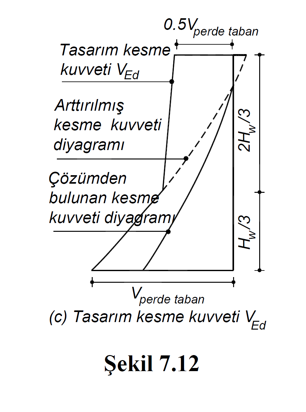
The shear forces in the graph shown in TBDY Figure 7.12 (c) are explained below.
"The shear force diagram found from the solution" is the shear force diagram calculated under the combined effect of vertical loads and earthquake loads.
The diagram shown with the "increased shear diagram" is the shear force diagram resulting from the increment mentioned in the TBDY Article 7.6.6.3 . In this shear diagram, Equation. The shear force and vertical loads calculated by (7.16) are compared with the shear force value obtained by increasing the shear force calculated from the earthquake according to Section 4 by 1.2D (gapless walls) or 1.4D (bond beam walls) and the smaller shear force is taken into account. taken. This check is done for all loading combinations and the most unfavorable condition is taken into account.
The diagram shown with "Design shear force V Ed " is the same diagram as the "Increased shear diagram" in the region of H w / 3. H w / 3 In the region above the H w / 3 points in enhanced shear-shear force is taken as half the wall base at the highest point of the screen is the shear force generated in combination with a linear line. This check is done for all loading combinations and the most unfavorable condition is taken into account.
These shear forces are calculated at the center of gravity of the polygon curtain. Then this shear force is distributed to the arms of the polygon curtain in accordance with the shear force direction, taking into account the shear shear areas.
In TBDY Figure 7.12 (c) , H w is the total curtain height measured from the top of the foundation or from the ground floor slab. l w is the plan length of one arm of the polygon curtain. Since the length (l w ) of each arm of polygon curtains may be different from each other, H w / l w values are calculated on the basis of arm.
Considering the TBDY Article 7.6.6.3 and the TBDY Figure 7.12 (c) , three situations arise when the polygonal bulkheads have the design shear force.
-
Polygon Shearwalls in the Lower Zone of H w / l w > 2.0 and H w / 3
Design shear force, V e , to be taken as basis in the transverse reinforcement calculation for walls meeting the condition H w / l w > 2.0 , of polygon wall arms according to TBDY Article 7.6.6.3 shall be calculated by Equation 7.16 .

In this equation (M p ) t means the moment capacity calculated by considering the strength increase of f ck , f yk and steel in the base section of the polygon wall . This value is calculated by moment curvature analysis for the entire polygon wall. This value is also the moment of power consumption of the group curtain section. (M d ) t , vertical loads in load multiplied by the base section and the polygon screen means torque calculated under the combined effect of earthquake loads. Here, the results of the finite elements of the polygon wall are summed at the center of gravity of the wall section to satisfy the three-dimensional rigid body motion condition, and (M d ) tvalue is obtained. V d value is the shear force value on each branch of the polygon wall calculated under the combined effect of vertical loads and earthquake loads multiplied by the load coefficients. The shear force in this equation is taken as the dynamic magnification coefficient β v = 1.5. Β v = 1.0 is taken for buildings where all earthquake load is carried by reinforced concrete curtains .
However, with the vertical loads, the shear force obtained by increasing the shear force found in the earthquake calculation by 1.2D (gapless walls) and 1.4D (bond beam walls) creates an upper limit. Therefore, if the shear force considered with 1.2D or 1.4D is smaller than the shear force value found by TBDY Equation 7.16 , this shear force is used as the Design Shear Force. This check is done for all loading combinations and the most unfavorable condition is taken into account.
As can be understood from the above explanation, while calculating the moment capacity in polygon walls, the entire polygon curtain is taken into consideration while calculating the design shear force, the shear strength from the whole polygon wall to a single arm.
-
Shearwalls in the upper region of H w / l w > 2.0 and H w / 3
In the polygon walls that meet the condition H w / l w > 2.0 and located in the upper region of the height H w / 3 in the shear force diagram , the linearized design shear force value shown in TBDY Figure 7.11c is used in addition to the control performed using TBDY Equation 7.16 . In this graph, the shear force value to be used in the upper section of the wall is taken as half of the design shear force at the base of the curtain. H w / 3 The design shear force at the height of the curtain section and the shear force value at the top point of the curtain are combined with a linear line and the design shear forces in other sections are found. This check is done for all loading combinations and the most unfavorable condition is taken into account.
The design shear force V e value of the polygon walls in the upper part of H w / 3 is found with the linearized graph described above. After the shear force coming to the center of gravity of the polygon curtains is found by this method, the Design Shear Force, V e , of the polygon curtain arms is distributed to the polygon curtain arms in accordance with the shear force direction, taking into account the shear areas. This check is done for all loading combinations and the most unfavorable condition is taken into account.
-
Shearwalls with H w / l w ≤ 2.0
Design shear forces of polygonal walls with H w / l w ≤ 2.0 according to TBDY Article 7.6.6.3 are taken equal to shear forces calculated according to TBDY Section 4 . The shear force value calculated under the combined effect of the vertical loads and the earthquake loads increased with the Resistance Excess Coefficient D is used as the design shear force, V e . These shear forces are calculated in the center of gravity of the polygon walls and distributed to the polygon curtain arms in accordance with the shear force direction, taking into account the shear areas. This check is done for all loading combinations and the most unfavorable condition is taken into account.
Related Topics