
The displaced axis rotation values are used in linear performance analysis to calculate the strain and plastic rotation demands of columns, beams and shear elements.
ICONS
E = Concrete modulus of elasticity
h = Section height
I = Moment of inertia
l c = Element net opening
l s = Shear opening
M y = Effective yield moment
M yi = Effective yield momentat i end
M yj = Effective yield moment at end j
Δ = Element node points to shift
φ y = Yield curvature
φ t = total curvature
θ p =Plastic rotation demand
θ i = i joint rotation
θ j = j node rotation
θ y = flow rotation
θ yi = flow rotation at end i
θ yj = flow rotation at end j
θ k = displaced axis rotation
θ ki = displaced axis rotation at end i
15A.1. DEFINITIONS
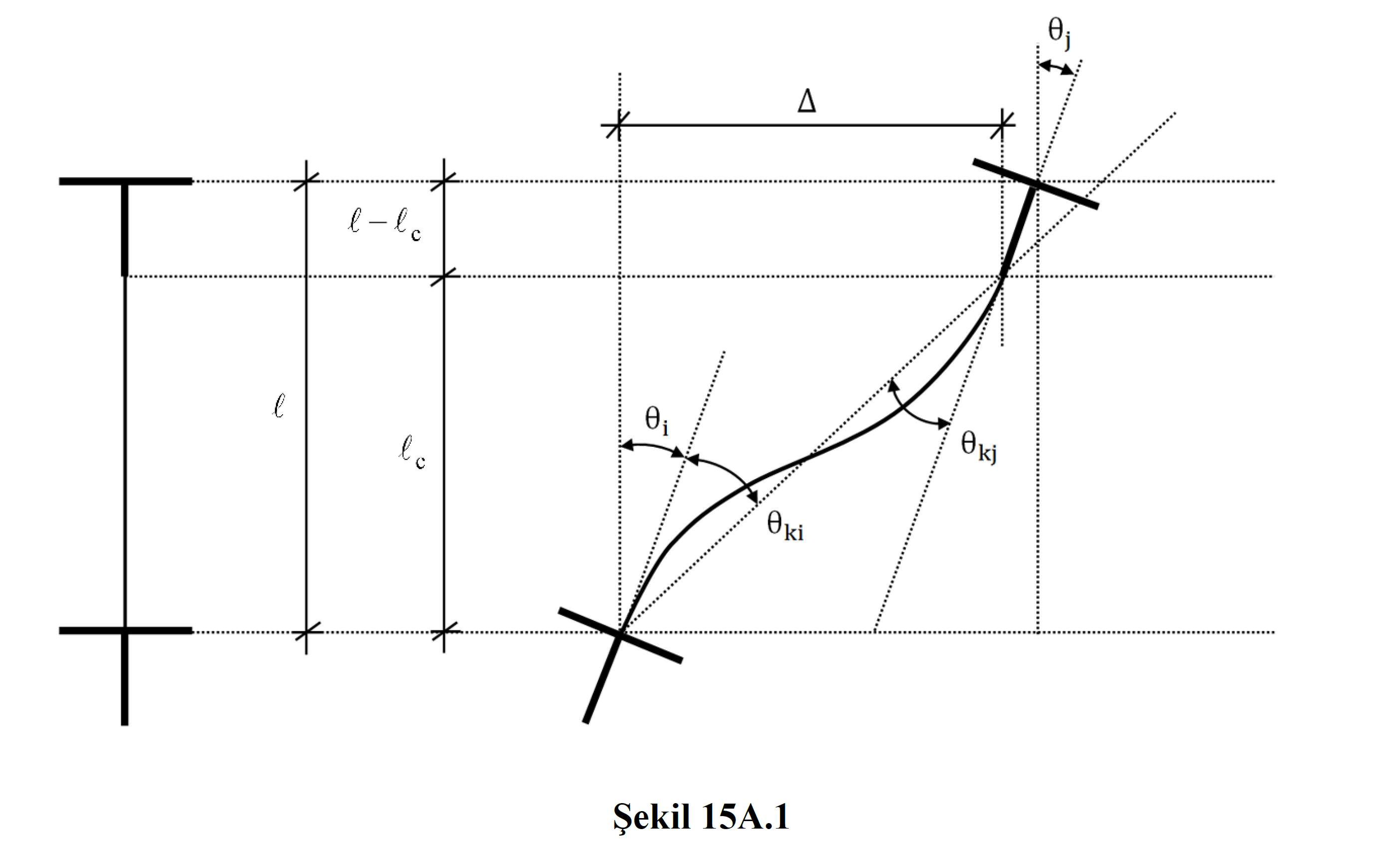
The deformation properties of a typical bending element under double curvature bending are shown in Figure 15A.1 . Here, l is the total length of the element, l c is the net span, Δ is the displacement between floors, θ i and θ j are the rotations of joints i and j, respectively, θ ki and θ kj are the displaced axis rotations at the ends i and j, respectively.
15A.2. REPLACED AXIS ROTATION
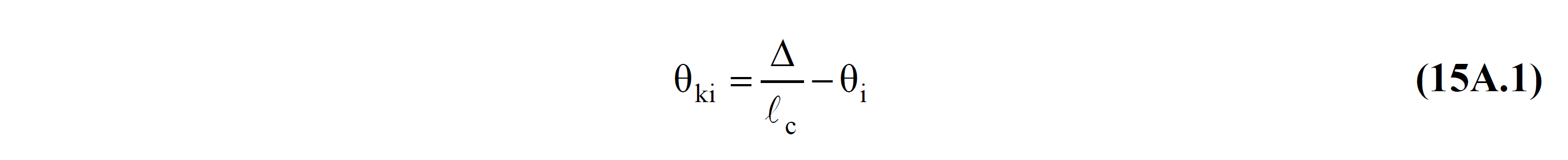
When the bending element is in the linear elastic deformation state, the relation of displaced axis and joint rotations at the i end and the displacement between floors is defined in Equation (15A.1) .
In beam elements, the translational value between floors can generally be taken as zero (= 0). When flow occurs at the i end of the element, the total displaced axis rotation at the i end is equal to the sum of the flow rotation and plastic rotation at this end.

15A.3. FLOWING ROTATION IN FRAME ELEMENTS
The relations between the tip yield rotations and end moments at the i and j ends of a bending element that has become flowing at both ends are given in Equation (15A.3) . The definition of yield rotations for elements with both ends in flowing state corresponds to the most unfavorable situation in the calculation of unit deformation demands according to 15.5.4 .
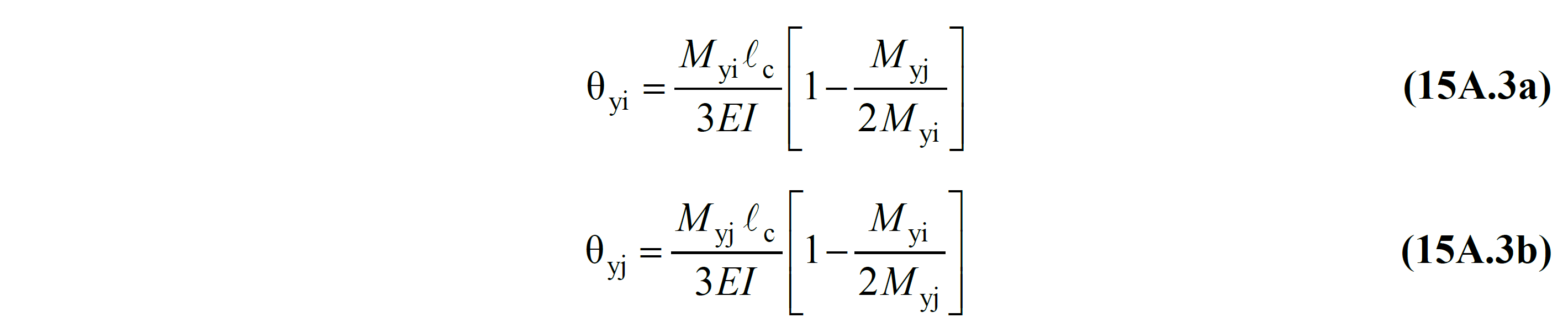
In Eq. (15A.3) , EI is the bending stiffness of the uncracked section , M yi and M yj are the effective yield moments at the i and j ends , respectively. The directions of the yield moments are counterclockwise plus, and minus clockwise. Therefore, Equation (15A.3) includes both double and single curvature bending cases. The effective yield moment M y , Annex 5A.1 'will be obtained according to the definition given.
15A.4. FLOWING ROTATION IN CURTAIN ELEMENTS
The relationship between the yield rotation and the yield moment of a bending element defined as a curtain according to 4.5.3.2 at the lower end of any floor of the building is given in Equation (15A.4) .
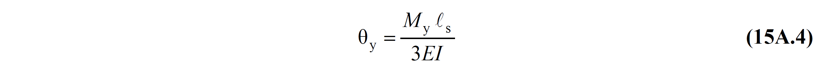
Where l c is the shear gap (ratio of moment / shear force in cross section). It can be taken as approximately half the distance from the base of each floor to the top of the curtain.
Next Topic