
It is not possible to send the images in the view, perspective and axonometric perspective windows directly to the printer/plotter. With the Generate Vector Drawing command, vector drawings of the views here, are created and the drawing output is taken.
A new 2-dimensional window will be opened and the view in the respective view / perspective window will be vectorially created here. This drawing can be intervened in two dimensions.
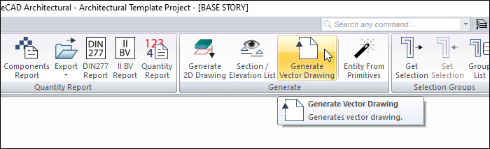
Location of the Generate Vector Drawing Command
In the Architectural Program
You can access it under the ribbon menu Tools tab, Generate heading.
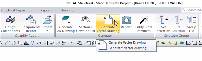
In the Structural Program
You can access it under the ribbon menu Tools tab, Generate heading.
Usage Steps
-
Click the Generate Vector Drawing icon in the elevation/perspective window .
-
The Generate Vector Drawing dialog will appear. After making the desired selections, click on the OK button.
-
Your vector drawing will be created.
|
Model in 3d window 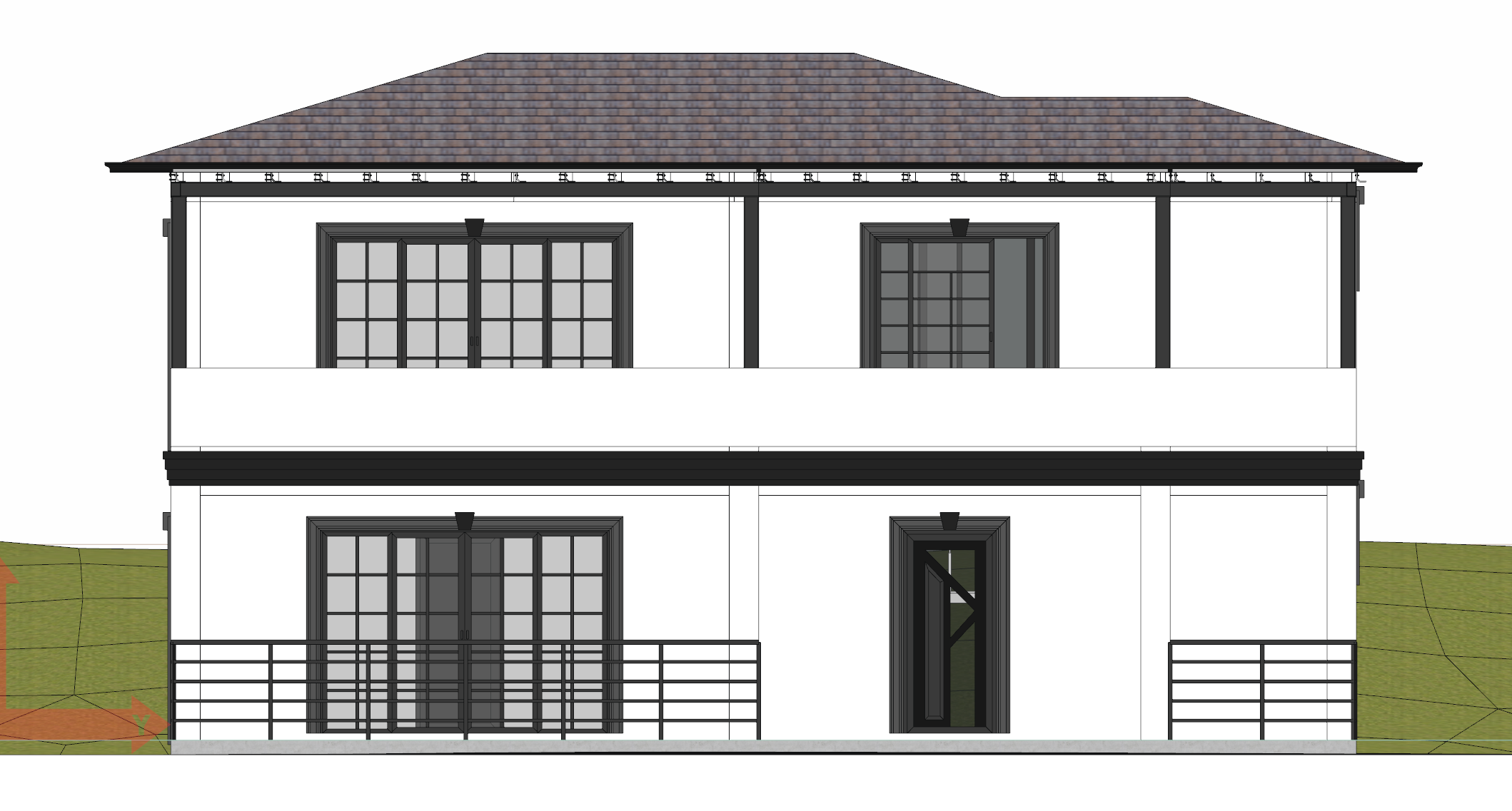
|
|
Vector illustration 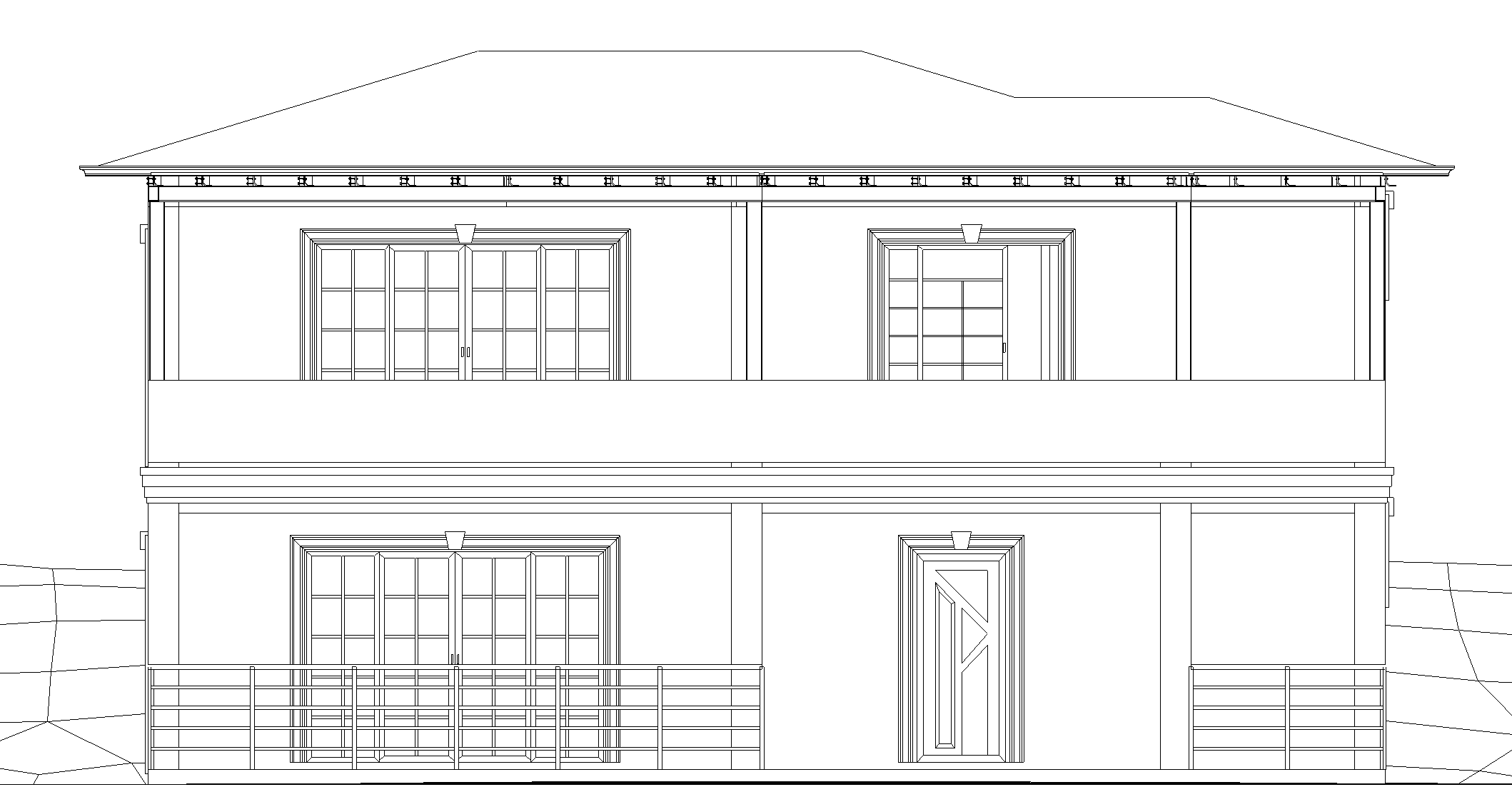
|
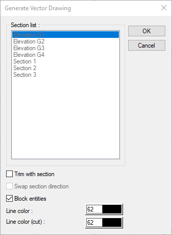
Generate Vector Drawing
|
Specifications |
|---|
|
Section list 
The sections in the project are listed. It becomes active when the Trim with section option is checked. |
|
Trim with section Transfers the project to the vector drawing by cutting with the selected section line. |
|
Swap section direction Transfers objects opposite to the viewing direction of the selected section to the vector drawing. |
|
Block entities Converts the drawings into blocks and transfers them to vector drawing. |
|
Line color The color of the drawings transferred to the vector drawing is selected. |
|
Line color (cut) Color of cut drawings is selected from drawings transferred to vector drawing. |
Next Topic