
Symbols
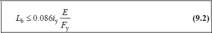
iy : Radius of gyration with respect to the weak axis of the beam cross-section
E: Modulus of elasticity of structural steel
Fy : Characteristic yield stress of structural steel
Lb: Length between points which are either braced against the lateral displacement of compression flange or braced against twist of the cross-section
In a way, with this control, the secondary beam placement and structural stability are determined.
-
Both flanges of the beam of steel frames that transfer moment must be supported at certain intervals. The aim here is to support the beam laterally to prevent buckling and to allow the formation of plastic hinges in areas whose capacity is preserved. In this way, the entire capacity of the beam is used.
-
In TBDY 2018 Annex 9B, the lengths of the plastic hinges and the location of formation of plastic hinges are defined. These sections, which are called as the protected zones are defined as the zone that will absorb energy under reversible effects such as earthquakes. Therefore, in order to benefit from the capacity of these regions, the beams must be supported laterally.

-
In accordance with the condition given in Eq. 9.2, it should be supported against lateral buckling with lateral support elements.
-
In steel frames where reinforced concrete slabs work as a composite with steel beams, this condition is not required for the flanges of the beams connected to the reinforced concrete slabs.
-
ideCAD Structural applies and reports this control automatically.
Next Topic