
The Bezier command creates a bezier curve in the project. Bezier curve design is made by defining more than one point.
Location of the Bezier Command
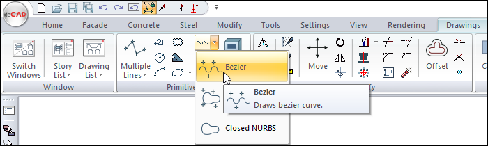
In the Architectural Program
You can access it under the ribbon menu Drawings tab, Primitive title
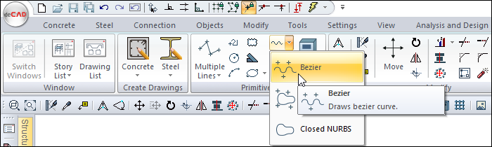
In the Structural Program
You can access it under the ribbon menu Drawings tab, Primitive title.
Usage Steps
-
Click the Bezier icon in the ribbon menu .
-
Click with the left mouse button in the drawing area to determine the wanted number of points.
-
As you identify the points, the Bezier curve will also shape according to the location of the points.
-
Click the right mouse button to finish drawing the curve.
|
Usage step |
|---|
|
Determining the first point of the Bezier 
|
|
Determining the second point of the Bezier 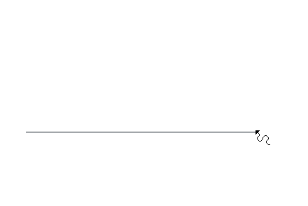
|
|
Determining the third point of the Bezier 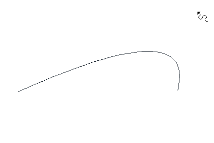
|
|
Determining the fourth point of the Bezier 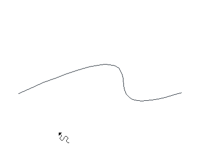
|
|
Bezier formation 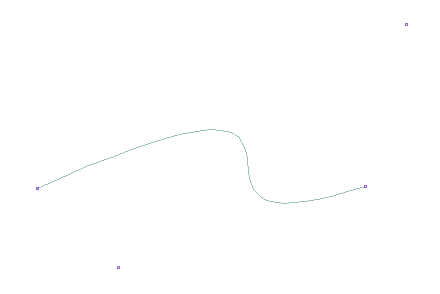
|
Location of the Bezier Settings Dialog
Bezier Command Settings
After running the Bezier command, you can access it by clicking the Settings icon in the Curves utility toolbar that appears on the screen.
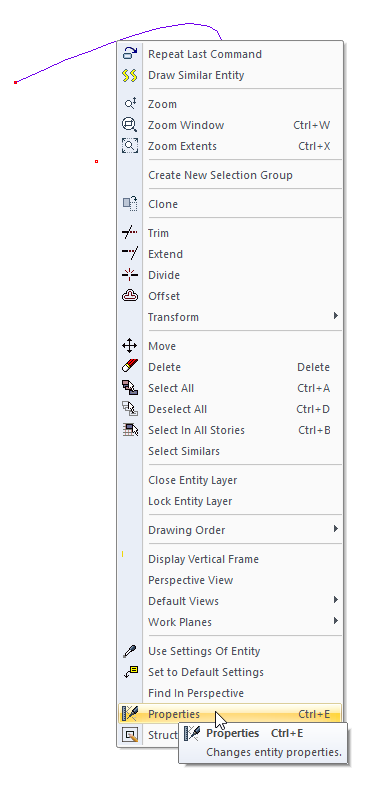
Bezier Object Settings
Select the cloth you want to enter its settings, click the right button of the mouse and click the Properties line from the menu that opens.
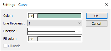
Bezier (Curve) Settings
|
Specifications |
|---|
|
Color Sets the color of the bezier. When the color box is clicked, the appropriate color is selected from the window that opens. |
|
Line thickness Line thickness is selected. The appropriate thickness is selected from the drop-down list when the down arrow button next to the box is clicked. The thickness selected here is only valid on the screen. It does not affect drawing printouts. |
|
Linetype Line type is selected. When the down arrow button next to the box is clicked, the appropriate line type is selected from the drop-down list. |
Next Topic
Related Topics