
-
Earthquake calculation is made automatically using TKB (CQC) with the mode combination method specified in TBDY 4B.2 .
ICONS
f ixn,max (X) = (X) the largest modal earthquake load acting on the i th floor in the nth natural vibration mode in the x axis direction of the building
H i = The upper part of the i th floor in the upper part above the basement floors of the building
M oxn ,max (X) = Variation of modal base overturning moment with respect to time in nth vibration mode under the joint effect of (X) and (Y) earthquake ground motion components at the same time
m i = i th floor total mass
m iθ = mass moment of inertia of the i th floor
m ixn (X) = (X) i'th floor modal effective mass of the building in the x-axis direction of the building in the x-axis direction
m iyn (X) = (X) of the nth natural vibration mode of the building in the y-axis direction of the building for the (X) earthquake direction i' th floor modal effective mass
m iθn (X) = (X) i th floor modal effective mass moment of inertia pertaining to the nth natural vibration mode of the building around the z axis for the earthquake direction
m j (S) = Typical finite element nodal point j'
m t = total mass of the upper section of the building above the basement floors
m txn (X) = (X) base shear modal effective mass of the building in the x-axis direction of the building for the earthquake direction
m tyn (Y) = (Y) the base shear modal effective mass of the building in the y-axis direction for the earthquake direction
r max (X) = ( X ) combined typical largest modal response magnitude corresponding to any response magnitude (displacement, relative story drift, internal force component) for the earthquake direction Typical unit modal behavior quantity corresponding to a behavior quantity (displacement, relative story translation, internal force component)
r n,max (X) = typical largest modal response magnitude corresponding to any response magnitude (displacement, relative story drift, internal force component) for the earthquake direction in the nth natural vibration mode (X)
S aR (T n ) = n Reduced design spectral acceleration of the 'th vibration mode
T n = the natural vibration period of the nth mode
V txn,max (X) = (X) the largest modal base shear force YM of the nth vibration mode in the x-axis direction of the building for the earthquake direction = Sufficient number of vibration modes
β mn = ratio of mth and nth natural vibration periods
Γ n (X) = (X) modal contribution factor of nth vibration mode for earthquake direction
ξ n = modal damping rate of nth vibration mode
ω n = n Natural vibrational angular frequency of the 'th vibrational mode
ρ mn = Cross correlation coefficient of the m'th and nth natural vibrational modes in the Perfect Quadratic Coupling Rule
While calculating the earthquake with the mode combination method, the horizontal elastic design spectrum is used in the direction of a given earthquake, and the maximum values of the behavior magnitudes in each considered vibration mode are calculated by the modal calculation method. The largest non-simultaneous modal response quantities calculated for enough vibration modes are then statistically combined to obtain approximate values for the largest response modes.
For each vibration mode considered, the largest modal behavior quantities, namely displacements, relative story translations, internal forces and stresses, are found. The largest modal behavior magnitudes found are Perfect Quadratic CouplingThey are combined using the (CQC) rule. In this analysis, it does not provide information about when the magnitude of behavior in question occurs and its correlation with other attributions. The values found as a result of the combination reveal the largest possible positive (absolute) value for a single modal behavior quantity. For this reason, the concept of direction is lost in the earthquake calculation made with the mode combining method.
The Unit Modal Behavior Magnitude specified in TBDY 4B.1.6 is the magnitude corresponding to any behavior magnitude (displacement, relative story drift, internal force component) in the typical n'th vibration mode for the given (X) earthquake direction. TBDY is obtained by a static calculation in which the modal effective masses defined in Equation 4B.2 are acted as charges in their own direction. All 6 degrees of freedom together with the (X) direction are used for modal analysis in three-dimensional systems. For this reason , (Y), (Z), (RX), (RY) and (RZ) values are also calculated for the (X) terms defined in TBDY Equation 4B.2 .
According to TBDY 4B.2.3 In a typical nth vibration mode for a given earthquake direction (X), the typical largest modal response magnitude r n,max (X ) corresponding to any response magnitude (displacement, relative story translation, internal force component) ) is calculated by Equation (4B.3) .
Here , the typical unit modal response magnitude defined in 4B.1.6 , and S aR ( Tn ) represents the reduced design spectral acceleration obtained from Eq.(4.8) for the typical n'th natural vibration period Tn .
With this equation, the maximum values of the behavior variables such as internal force components, displacement and relative story drift are calculated for each vibration mode. However, since the largest modal contributions are asynchronous magnitudes, they are combined statistically. Any behavior magnitude (displacement, relative story translation, internal force component) can be reached by applying the Perfect Square Joining rule. As the most common mode coupling rule, Perfect Quadratic Coupling (TKB or CQC) is calculated by TBDY Equation 4B.4 .
In the above equation , the cross-correlation coefficient , ρ mn , is calculated as in TBDY Equation 4B.5a .
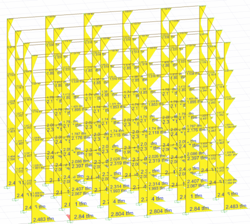
For any (X) earthquake direction, the largest modal response magnitude, r max (X) , is the displacement, relative story drift, and internal force component values. These values are the largest positive (absolute)Since there are values, the concept of direction disappears in this method. Therefore, when examining the results of the mode coupling method analysis (eg Ex internal force diagram), the values shown on the structure do not provide the equilibrium equation. The values seen in the analysis results are the highest possible value of the point of view. In the image below, there are M3 moment results calculated with the mode combination method for the Ex earthquake. As can be seen, there is no negative direction and the equilibrium equation is not met. Because these values on Ex results show the highest M3 value calculated by considering all modes of the relevant point.
The mode combination method is also used when calculating the Base Overturn Moment of the Curtains specified in TBDY 4.3.4.8 . In a typical n'th vibration mode for earthquake direction (X) given according to TBDY 4B.2.5 , the largest modal base shear force V txn,max (X) of the carrier system in the x-axis direction and the corresponding largest base overturning moment M oxn, max (X) is calculated with Eq.(4B.7) :
Next Topic