
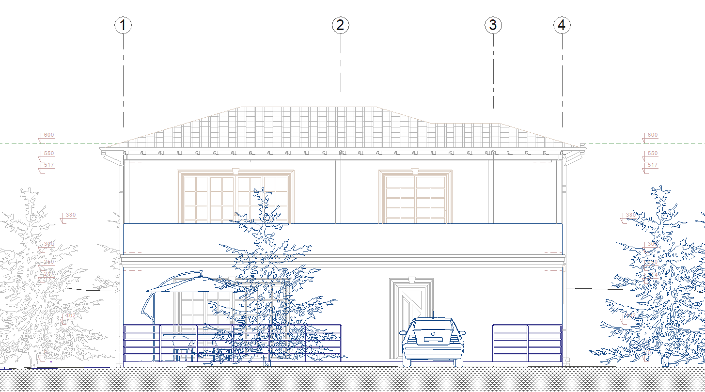
With the Elevation Line command, automatic view drawings are created according to the line passed outside the building. All objects that are in the plane according to the location of the drawn line are considered as cut objects, and other objects in front of the plane are considered as visible objects. ideCAD automatically separates the section and the elevation, but the section line should be drawn if a section is desired, and the elevation line should be drawn if a elevation is desired.
Location of the Elevation Line Command
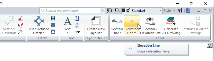
In the Architectural Program
You can access it under the ribbon menu Drawings tab, Tools heading.
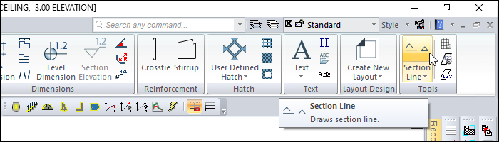
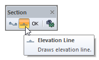
In the Structural Program
After entering the Section command under the Tools title of the ribbon menu drawings tab, you can access the Elevation command from the Section toolbar .
Usage Steps
-
Click the Elevation icon.
-
Specify the elevation line by clicking two points in the drawing area.
-
To specify the viewing direction, click on the side of the elevation line you want to display .
-
A line of sight will be formed.
-
Double-click the drawn elevation line.
-
Elevation Settings will open. Make any adjustments you want from the elevation settings dialog.
-
When you click the Generate button, the view will be created.
|
Usage step |
|---|
|
Determining the first point of the line of elevation 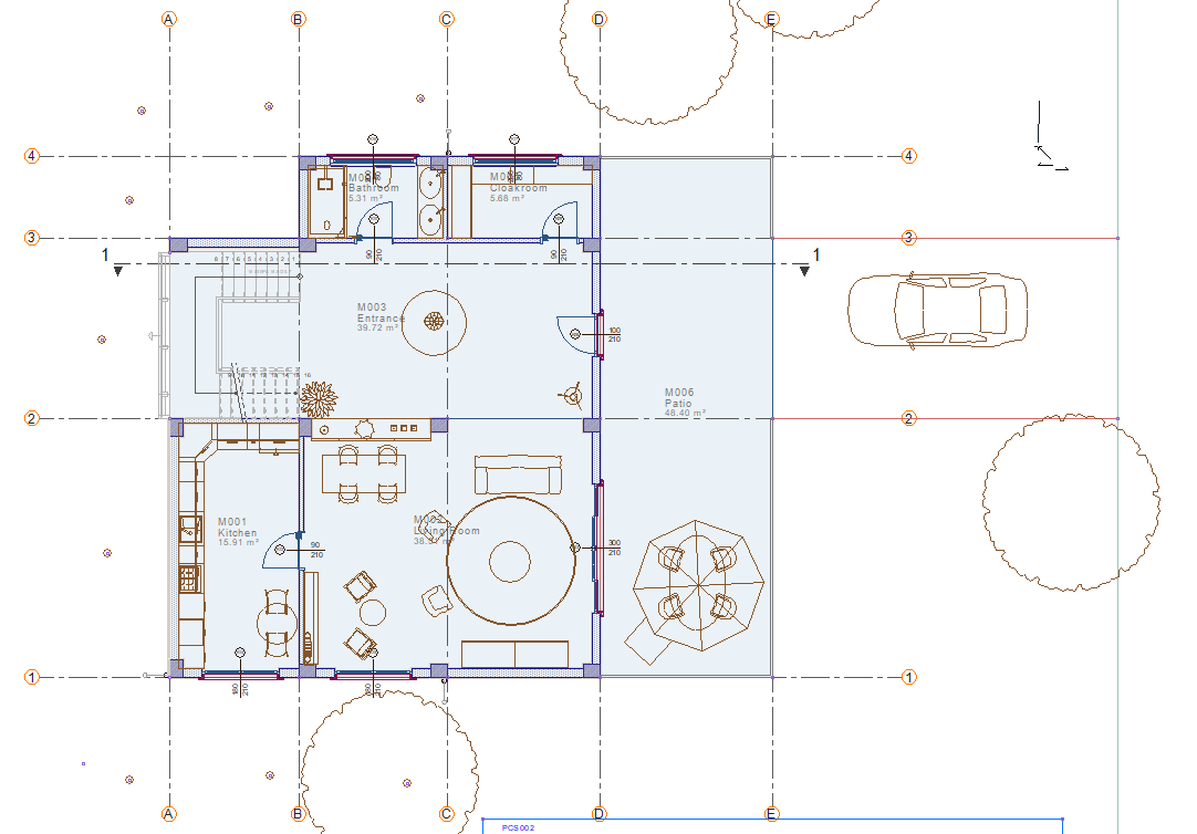
|
|
Determining the second point of the line of elevation 
|
|
Determining the viewing direction 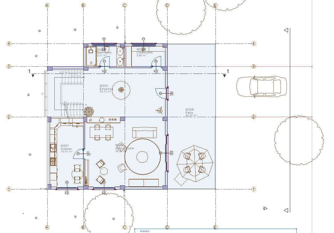
|
|
The formation of the line of elevation 
|
|
Creating the elevation 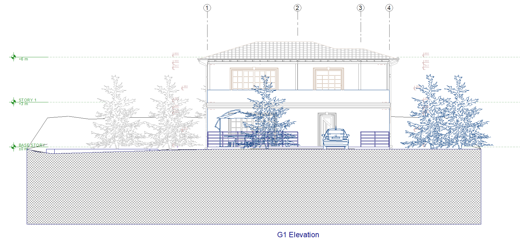
|
Next Topic