
How does ideCAD design steel members subject to flexure and axial force according to AISC 360-16?
-
Steel members subject to flexure and axial force is designed automatically according to AISC 360-16.
-
The interaction of flexure and compression is calculated automatically according to AISC 360-16.
Symbols
Pr = required axial strength determined using LRFD or ASD load combinations, kips (N)
Pc = available axial strength, kips (N)
Mr = required flexural strength, determined using LRFD or ASD load combinations, kip-in. (N-mm)
Mc = available flexural strength, kip- in. (N-mm)
x = subscript relating symbol to major axis bending
y = subscript relating symbol to minor axis bending
The interaction of axial load and bending may be investigated by using elastic methods that consider the simple combination of the stresses from axial load and bending moments.
The strength calculation considers the combined stresses created in the elements under flexural and axial force. The superposition of the stresses only applies to similar stresses. The superposition rule does not apply to stability losses.
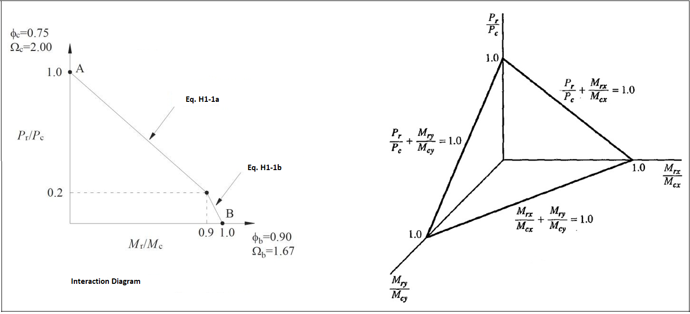
Equation H1.1 is used for biaxial and single symmetry axis members under the influence of axial compression and flexural moment.
Flexural design is explained under the title of Design of Steel Members for Flexure per AISC 360-16 §F
Compression design is explained under the title of Design of Steel Members for Compression per AISC 360-16 §E
-
Design axial strength,
(LRFD)
-
Allowable axial strength
(ASD)
-
Design flexural strength,
(LRFD)
-
Allowable flexural strength
(ASD)