How does ideCAD calculate beam-column joint strength according to ACI 318-19?
-
Beam-column joint shear force Vu and joint design shear strength Vn are calculated automatically.
-
Beam-column joints of earthquake resistance structures are automatically designed per ACI Chapter 18
Download ideCAD for ACI 318-19
Notation
As = area of nonprestressed longitudinal tension reinforcement, in2
Aj = effective cross-sectional area within a joint in a plane parallel to plane of beam reinforcement generating shear in the joint, in.2
Cc = concrete compressive force, lb
db = Nominal diameter of bar, wire, or prestressing strand, in.
fc' = specified compressive strength of concrete, psi
√fc‘ = square root of specified compressive strength of concrete, psi
h = overall thickness, height, or depth of member, in.
lu = unsupported length of column or wall, in.
Mn = nominal flexural strength at section, in.-lb
Mpr = probable flexural strength of members, with or without axial load, determined using the properties of the member at joint faces assuming a tensile stress in the longitudinal bars of at least 1.25fy and a strength reduction factor ϕ of 1.0, in.-lb
Vn = nominal shear strength, lb
Vu = factored shear force at section, lb
(Vu)j = required joint shear force, lb
ϕ = strength reduction factor
λ = modification factor to reflect the reduced mechanical properties of lightweight concrete relative to normalweight concrete of the same compressive strength
According to ACI 15.4.1.1, the joint required shear force, Vu, should be calculated on a plane at a medium height of the joint using flexural beam forces and column shear consistent with one of the following cases;
-
The maximum moment transferred between the beam and column as determined from factored-load analysis for beam-column joints with continuous beams in the direction of joint shear considered
-
Beam nominal moment strengths Mn
According to ACI 15.4.2.1, the design shear strength ϕVn of the beam-column joint should satisfy the equation below.
Strength reduction factors ϕ is determined according to using ACI Table 21.2.1.
The beam-column joint's nominal shear strength Vn should be calculated per ACI Table 15.4.2.3.
|
Column |
Beam in direction of Vu |
Confinement by transverse beams according to 15.2.8 |
Vn, lb |
|---|---|---|---|
|
Continuous or meets 15.2.6 |
Continuous or meets 15.2.7 |
Confined |
|
|
Not confined |
|
||
|
Other |
Confined |
|
|
|
Not confined |
|
||
|
Other |
Continuous or meets 15.2.7 |
Confined |
|
|
Not confined |
|
||
|
Other |
Confined |
|
|
|
Not confined |
|
According to ACI 15.2.8, for a beam-column joint to be considered confined for the direction of joint shear, two transverse beams should be satisfied the following three conditions:
-
The width of each transverse beam is at least three-quarters of the width of the column face into which the beam frames
-
Transverse beams extend at least one beam depth h beyond the joint faces
-
Transverse beams contain at least two continuous top and bottom bars satisfying ACI 9.6.1.2 and No. 3 or larger stirrups satisfying ACI 9.6.3.4 and 9.7.6.2.2.
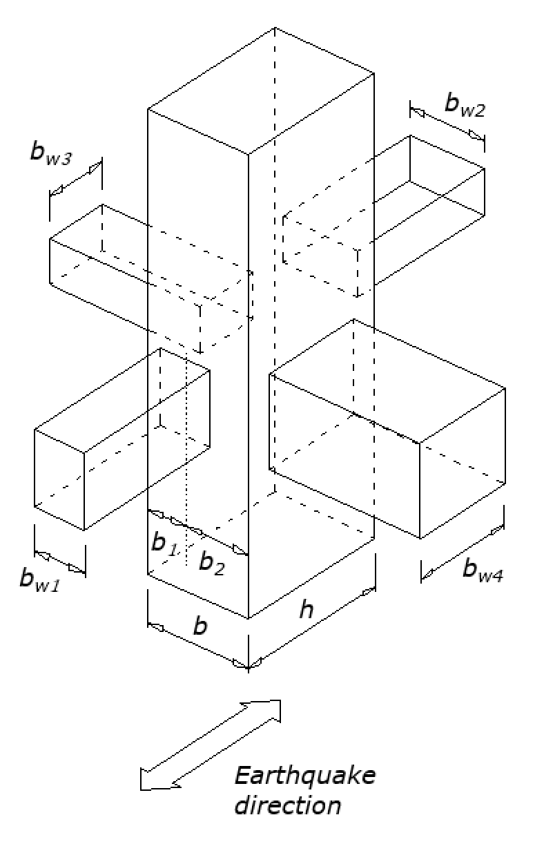
The effective cross-sectional area within a joint, Aj, equals joint depth times effective joint width. Joint depth is the overall depth of the column, h, in the direction of the joint shear considered. If the beam is wider than the column, effective joint width is the overall width of the column. If the column is wider than the beam, the effective joint width should not exceed the lesser of beam width plus join depth and Twice the perpendicular distance from the longitudinal axis of the beam to the nearest side face of the column. The effective cross-sectional area within a joint, Aj, is illustrated in ACI Fig. R15.4.2.
Beam-Column Joint Design for Earthquake-Resistant Structures
Ordinary moment frames
All the conditions and calculations described above are valid for joints of ordinary moment frames. Beam-column joint shear Vu is calculated on a plane at mid-height of the joint using beam forces and column shear consistent with beam nominal moment strengths Mn.
Intermediate moment frames
All the conditions and calculations described above are valid for joints of intermediate moment frames. Beam-column joints should satisfy the joint detailing requirements in Reinforcement Detailing of Joints per ACI 318-19 with ideCAD title.
According to ACI 18.4.4.7.1, the design shear strength ϕVn of the beam-column joint should satisfy the equation below.
According to ACI 18.4.4.7.2, Beam-column joint shear Vu is calculated on a plane at mid-height of the joint using beam forces and column shear consistent with beam nominal moment strengths Mn.
According to ACI 18.4.4.7.3, Strength reduction factors ϕ is determined using ACI Table 21.2.1.
According to ACI 18.4.4.7.4, Nominal shear strength Vn of beam-column joints should be calculated for joints of special moment frames.
Special moment frames
According to ACI 18.8.2.1, when calculating forces at the joint face, longitudinal beam reinforcement flexural tensile stress is assumed to be 1.25fy.
Beam-column joints should satisfy the joint detailing requirements in Reinforcement Detailing of Joints per ACI 318-19 with ideCAD title.
According to ACI 18.8.2.3, if longitudinal beam reinforcement extends through a beam-column joint, the minimum depth h of the joint shall be the maximum of the following conditions:
-
(20/λ)db of the largest Grade 60 or S420 longitudinal bar. (λ=1 for normalweight concrete)
-
26db of the largest Grade 80 longitudinal bar.
-
h/2 of ant beam framing into the joint and generating joint shear as part of the seismic-force-resisting system in the direction under consideration
According to ACI 18.8.4.1, the joint required shear force Vu should be calculated on a plane at a medium height of the joint using tensile and compressive beam forces caused by flexure and column shear consistent with beam probable flexural strengths Mpr.
Strength reduction factors ϕ is determined according to using ACI Table 21.2.1.
According to ACI 18.8.4.3, the nominal shear strength Vn of the beam-column joint should be calculated in accordance with ACI Table 18.8.4.3.
|
Column |
Beam in direction of Vu |
Confinement by transverse beams according to 15.2.8 |
Vn, lb |
|---|---|---|---|
|
Continuous or meets 15.2.6 |
Continuous or meets 15.2.7 |
Confined |
|
|
Not confined |
|
||
|
Other |
Confined |
|
|
|
Not confined |
|
||
|
Other |
Continuous or meets 15.2.7 |
Confined |
|
|
Not confined |
|
||
|
Other |
Confined |
|
|
|
Not confined |
|
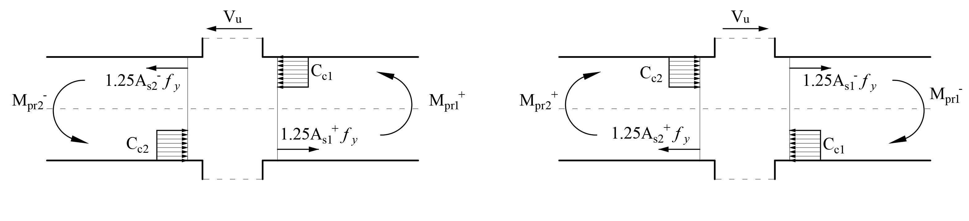
Calculation of the Joint Required Shear Force, (Vu)j
Joint required shear force (Vu)j should be calculated on a plane called panel zone at medium height of the joint using tensile and compressive beam forces caused by flexure and column shear consistent with beam probable flexural strengths Mpr. When calculating forces at the joint face, longitudinal beam reinforcement flexural tensile stress is assumed to be 1.25fy. Considering these conditions, the free-body diagram of the beam-column joint is shown in the picture below.