
Point load can be defined as external load on any element. Identification can be done with the Point Load command. Point load can be defined as force as well as moment .
Location of Point Load Command
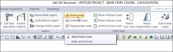
You can access it from the Add Load heading in the Modify tab in the ribbon menu .
Usage Steps
-
Click the Point Load command.
-
Click the column or beam element.
-
Click the right mouse button.
-
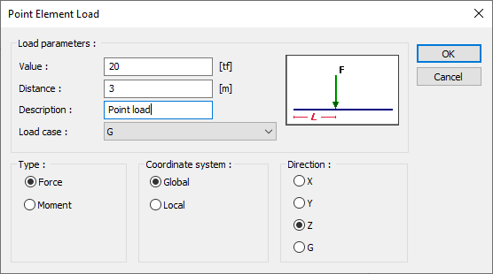
The Point Element Loads dialog will open.
-
Define the values by following the lines in the dialog.
Point Element Loads Dialog
|
Specifications |
|
Value (F) Enter the value of the load in the working unit. If you are looking at the properties of the current load, you will see that load value. You can change it according to the situation. |
|
Distance (L) Give the distance value from the bottom end for vertical elements and the left end for horizontal elements. If you are looking at the properties of the current load, you will see the previously entered value. |
|
Description If you are looking at the properties of the current load, the description of that load is shown. You can change it according to the situation. If you are defining a new load, write a description of the load you will define. |
|
Load case If you are looking at the properties of the current load, it is shown for which load case that load is valid. If you are adding a new payload, select from the list the load state to which the load you will define will apply. If the installation status is not defined in the system, the program will ask you to define it. |
|
Type 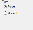
Check the defined load moment and force option. If you are looking at the properties of the current load, you will see the previously entered value. |
|
Coordinate system 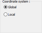
Specify whether the entered load values are given relative to the element local axes or to the global axes. |
|
Direction 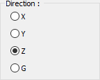
Provide information in which direction the load is valid. According to X, Y, Z global coordinate system, it shows the direction of the load according to 1,2 3 local coordinate axes. G indicates that this load is a constant (vertical) load. |
Axes according to the global coordinate system
The plus (+) direction is upwards, with the Z axis being the vertical axis (axis perpendicular to the paper plane).
If the constant weight is G, then Z is the negative (-) direction.
The X axis is the left to right direction, plus (+) direction on the paper plane. Y is the other axis perpendicular to the X axis in the paper plane and its positive direction is determined according to the right hand rule.
Axes relative to the local coordinate system
When looking at a beam in the plan, the axis parallel to the beam should be considered as the axis 1, the axis perpendicular to the beam 3 axis and the vertical axis 1 axis perpendicular to the working plane.
Similarly, in columns and walls, the 2 axis showing the strong direction of the column, the 3 axis showing the weak direction and the vertical axis perpendicular to the working plane should be considered as the 1 axis.
It is the positive (+) direction upwards in the Z axis and the directions of the other axes are determined according to the right hand rule.
Moments rotate their axis and the positive direction is determined by the right hand rule.
Next Topic
Related Topics