
Shear Connection design is made automatically according to the Design, Calculation, and Construction Principles of Steel Structures and AISC 360-16 (ASD and LRFD) regulations. Bolt, weld, plate, geometry, and strength controls are done automatically following the steel connection type.
A shear connection, also called a simple connection, is a joint that transfers shear forces between two members. It is a connection with pure normal force load (tension joint), pure shear loading, or a combination of normal and shear force. Shear connections are generally the most commonly used connections.
The Shear Connections in ideCAD Structural is a joint that transfers shear forces between a steel column and steel beam (or any other two steel members).
Shear connection types are listed below.
ideCAD Structural is an All-in-One Structural Engineering Software with Shear Connection and many other Integrated Building Information Modeling (BIM) tools.
Download ideCAD for Connection Design with AISC 360-16
The failure mechanisms and strength assumptions used in the design of shear connections and connection elements are found as follows according to ÇYTHYEDY 2018 and AISC 360-16 regulations.
Design Criteria for Shear Connection
-
It is assumed that the web of the cross-section resists the entire shear force.
-
There is no interaction between shear force and bending moment.
-
Shear strength is determined using the formula:
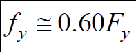
Shear Strength
-
In stiffened and unstiffened single and double symmetrical cross-sections, the characteristic shear strength in the web is calculated as follows:
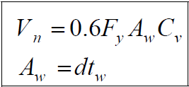
-
The coefficients for the I-cross section elements according to the slenderness ratio are determined as follows:
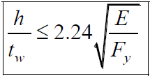
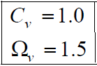
-
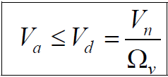
The allowable shear strength is calculated as follow:
Bearing Connections
-
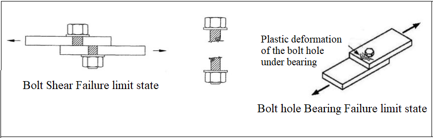
In the bearing connections, the strength is determined according to the smallest one by controlling 3 limit conditions.
-
Shear failure at the bolt.
-
Bearing limit state in the plate.
i) Tear-out limit state of the plate.
ii) Bearing limit state of the plate.
Characteristic Tensile and Shear Stress Strengths of Bolts
-
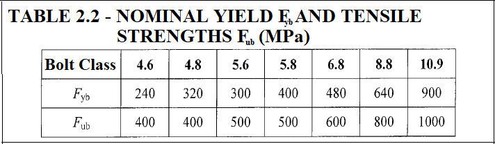
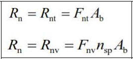
Characteristic tensile strength Fnt of bolts is calculated depending on the characteristic tensile strength of bolt material Fub given in Table 2.2.
-
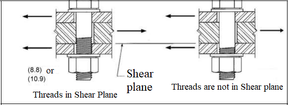
The characteristic shear stress strength of bolts, Fnv, is calculated in two different ways:
i) If the threaded part of the bolt is in the shear plane.
ii) If the threaded part of the bolt is outside of the shear plane.
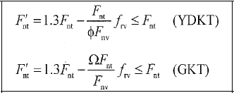
Characteristic Tensile Force Strength of Bolt Under the Combined Effect of Tensile and Shear Force
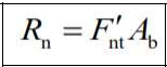
-
The characteristic tensile force or shear strength of prestressed high-strength bolts simply tightened bolts, and threaded cross sections are calculated according to the rupture limit state for the tensile forces and the tear-out limit state for shear forces.
Bearing Connections under the Combined Effect
Bearing Limit States in the Plate (Bolt Holes)
-
The compressive stresses that occur between the bolt and plate are because of excessive deformations on the bolt and plate.
-
To compute the bearing stress between the bolt and the hole edge, the assumption of uniform distribution of stresses on this surface is defined.
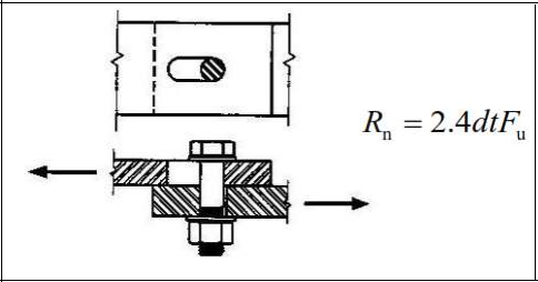
Bearing Failure of the Bolt Hole
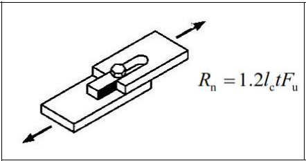
Tear-out Failure of the Plate
-
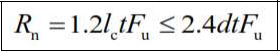
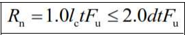
The characteristic bearing force resistance Rn of a bolt hole is calculated based on the bearing limit state under the shear effect as follows:
-
Regardless of the direction of the load, for connections formed from standard, oversized, and short-slotted holes or long-slotted holes with oval longitudinal axis parallel to the direction of the load:
-
For connections formed with slotted holes with oval longitudinal axis perpendicular to the direction of the load:
-
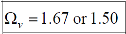
Safety factors depend on the method being used:
Shear Resistance
-
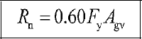
The characteristic shear strength Rn of the cross-section and connection elements under shear effect for the yield and rupture limit states are calculated as follows:
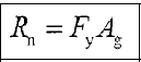
Yielding Limit State
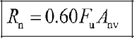
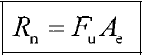
Rupture Limit State
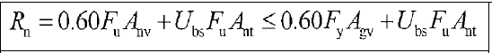
Block Shear Limit State
-
The characteristic block shear strength Rn is calculated based on the yield and rupture limit states along the shear surface or surfaces and the rupture limit states along the tensile surface.
Tensile Strength
-
The characteristic tensile strength Rn of the cross-section and connection elements under the shear effect for tensile action is calculated for the yield and rupture limit states as follows:
Yielding Limit State
Rupture Limit State
Symbols
Ab: Non-threaded bolt characteristic cross-sectional area
Aw: Cross-section web area
Ag: Gross area
Ae: Effective net area
An: Net area
Agv: Gross shear area
Anv: Net shear area
Ant: Net tensile area
Cv: Coefficient of reduction for shear buckling
d: Characteristic of bolt diameter
dh: Bolt hole diameter
Fy: Specified yield stress of the type of steel being used, ksi (MPa)
Fu: Specified ultimate stress of the type of steel being used, ksi (MPa)
Fnt: Characteristic tensile tensile strength given in Table 13.7
F'nt: Reduced characteristic tensile stress obtained by considering shear force effect
Fnv: Characteristic shear stress strength given in Table 13.7
frv: The greatest shear stress in the characteristic thread area of the bolt under LRFD or ASD load combinations
Fyb: Bolt characteristic yield strength
Fub: Bolt characteristic tensile strength
nsp: Number of shear planes
Ubs: A coefficient considering the distribution of tensile stresses
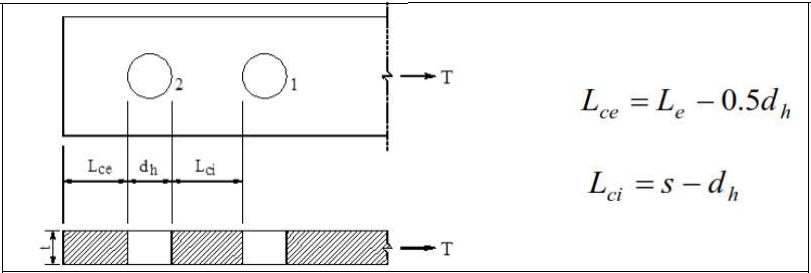
s: Distance between bolt holes center
Le: The distance from the center of the bolt hole to the edge of the connected element
t: Plate thickness
Rnt : Characteristic tensile strength
Rnv : Characteristic shear strength
Download ideCAD for Connection Design with AISC 360-16
Next Topic