
-
A2 - Floor Discontinuities: When the situation on any floor is marked by the user in the program
-
In buildings with A2 type irregularities, floor slabs are automatically modeled with two-dimensional plate (membrane) or shell finite elements to show that they can safely transfer earthquake forces between vertical bearing system elements within their own planes (See 4.5.6.2).
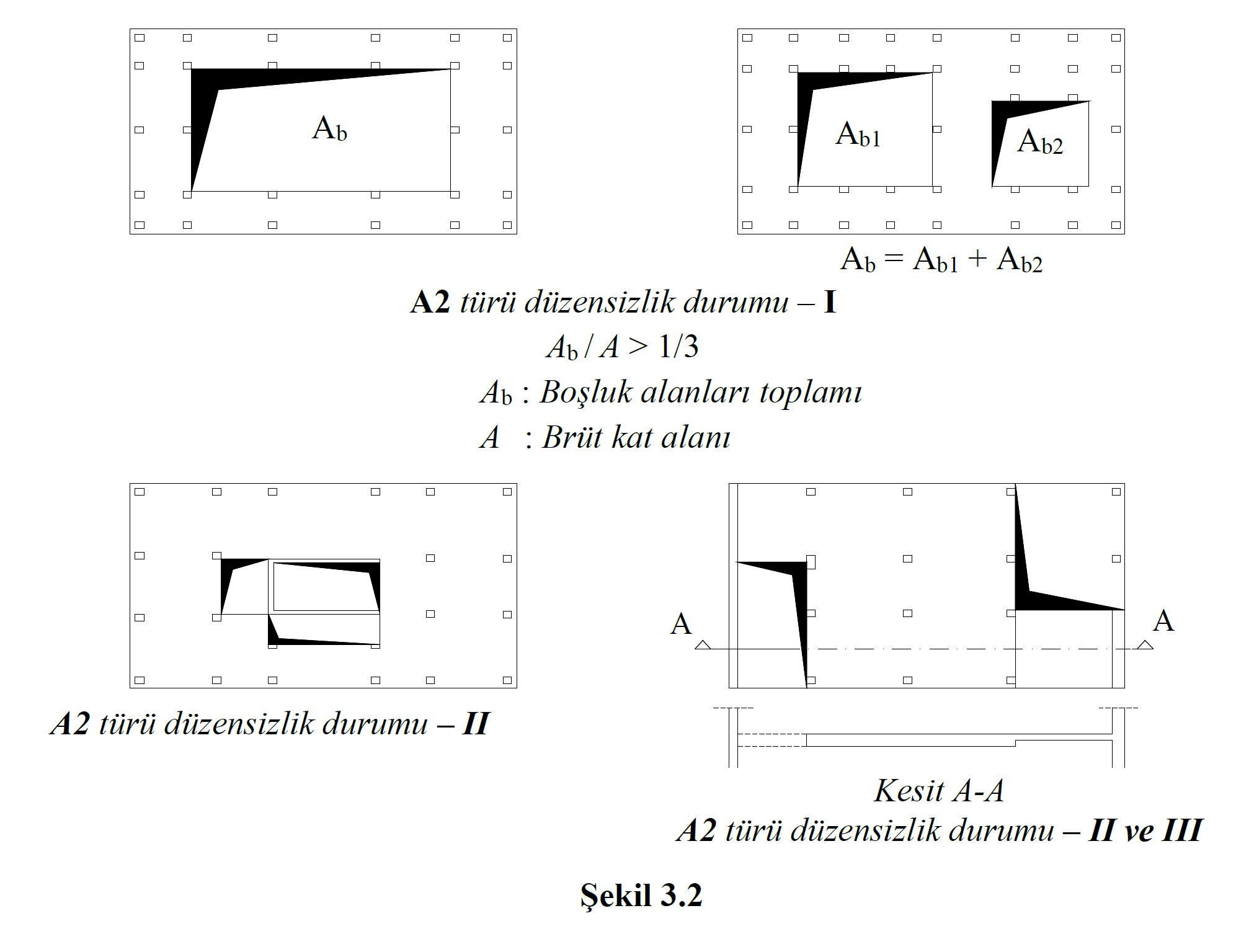
A2 type irregularity condition TBDY occurs when any of the following three items occur, as shown in Figure 3.2 .
-
The ratio of the total area of all spaces (including stairs and elevators) in the floor plan to the total floor gross area is more than 1/3.
-
The presence of local floor gaps that make it difficult to safely transfer earthquake loads to vertical bearing system elements.
-
Sudden decreases in in-plane stiffness and strength of slab
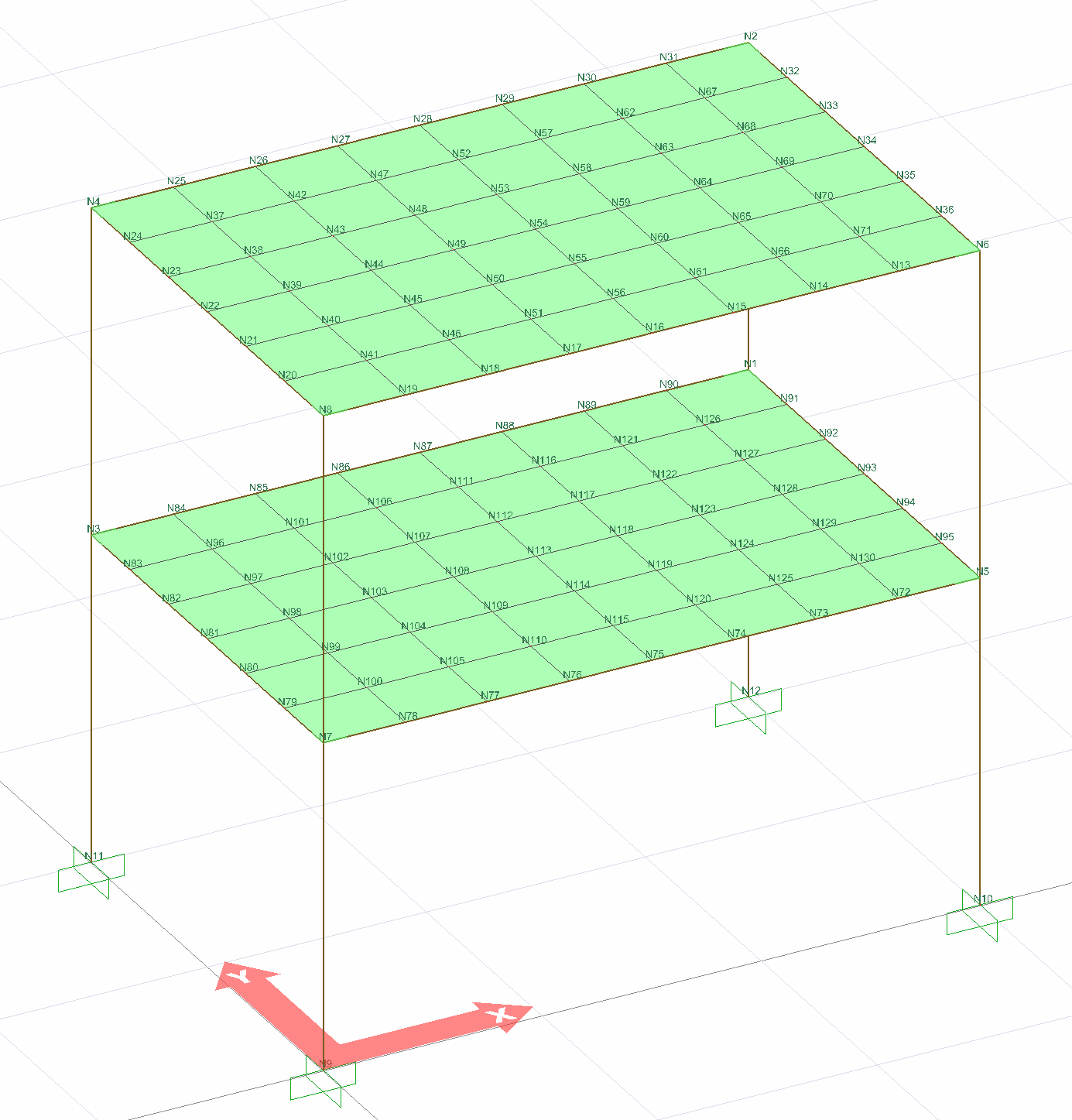
According to Article 3.6.2.2 and 4.5.6.2 of TBDY , floors in buildings with A2 and A3 type irregularities are modeled with two-dimensional finite elements. The following picture shows the analysis model of an example whose tiles are modeled with two-dimensional finite elements (shell).
As a result of three-dimensional analysis of shell finite elements (slabs, curtains and polygonal walls), they generate stresses and forces per unit length. The directions of these stresses and forces per unit length are determined according to the local axes of the shell finite element .
Shell finite element forces are obtained as a result of stresses formed by shell finite elements in three dimensional analysis.
-
M11, M22: Bending moments per unit length (tfm / m or kNm / m) formed around axes 1 and 2. They are also called out-of-plane bending moments.
-
M12: Means unit length planar torsion moment (tfm / m or kNm / m). It is also called the in-plane torsion moment.
-
V13, V23: Shell is the unit length shear forces (tf / m or kN / m) on the surface of the finite element and perpendicular to the plane of the finite element. It is also called the out-of-plane shear force.
-
F11, F22: Tensile and compressive forces per unit length (tf / m or kN / m) parallel to the plane of the acceptance finite element in the respective direction. It is also called in-plane pressure-pull forces.
-
F12: Unit length shear forces (tf / m or kN / m) parallel to the shell finite element plane. It is also called in-plane shear forces.
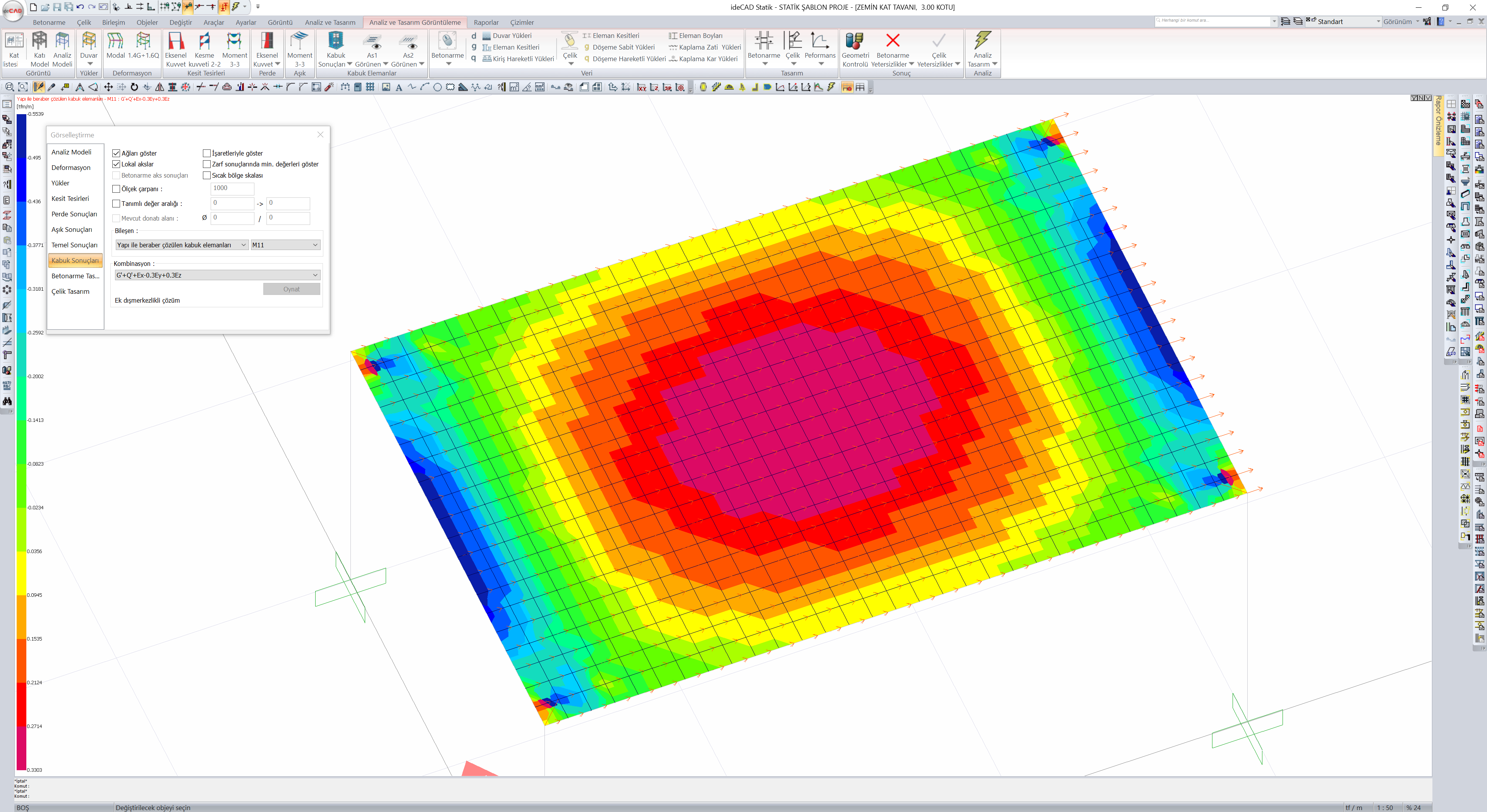
Shell finite element results can be viewed from the "Shell Results" tab in the Analysis Model.
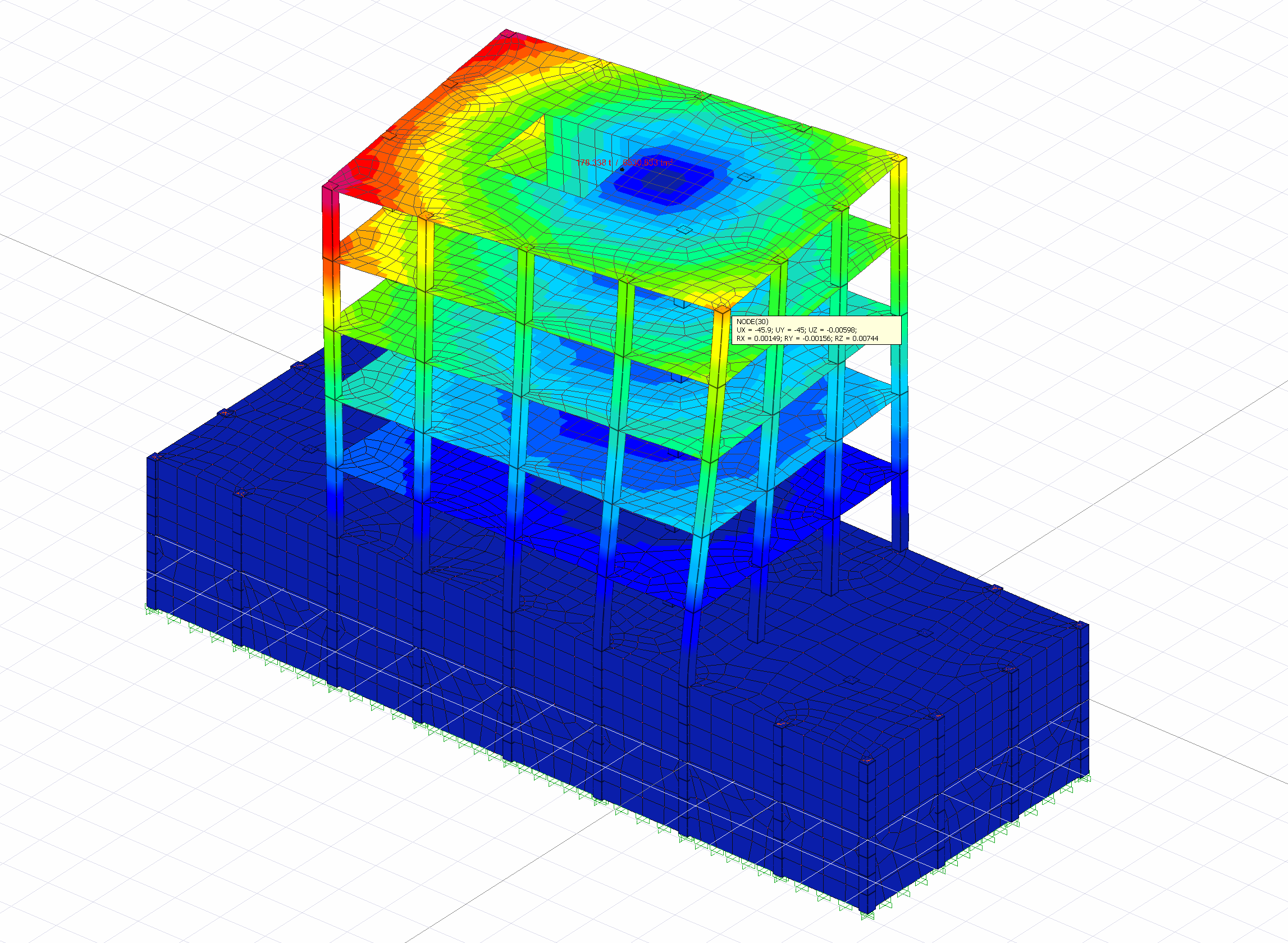
Deformation results from shell finite element results can also be examined in the Analysis Model.
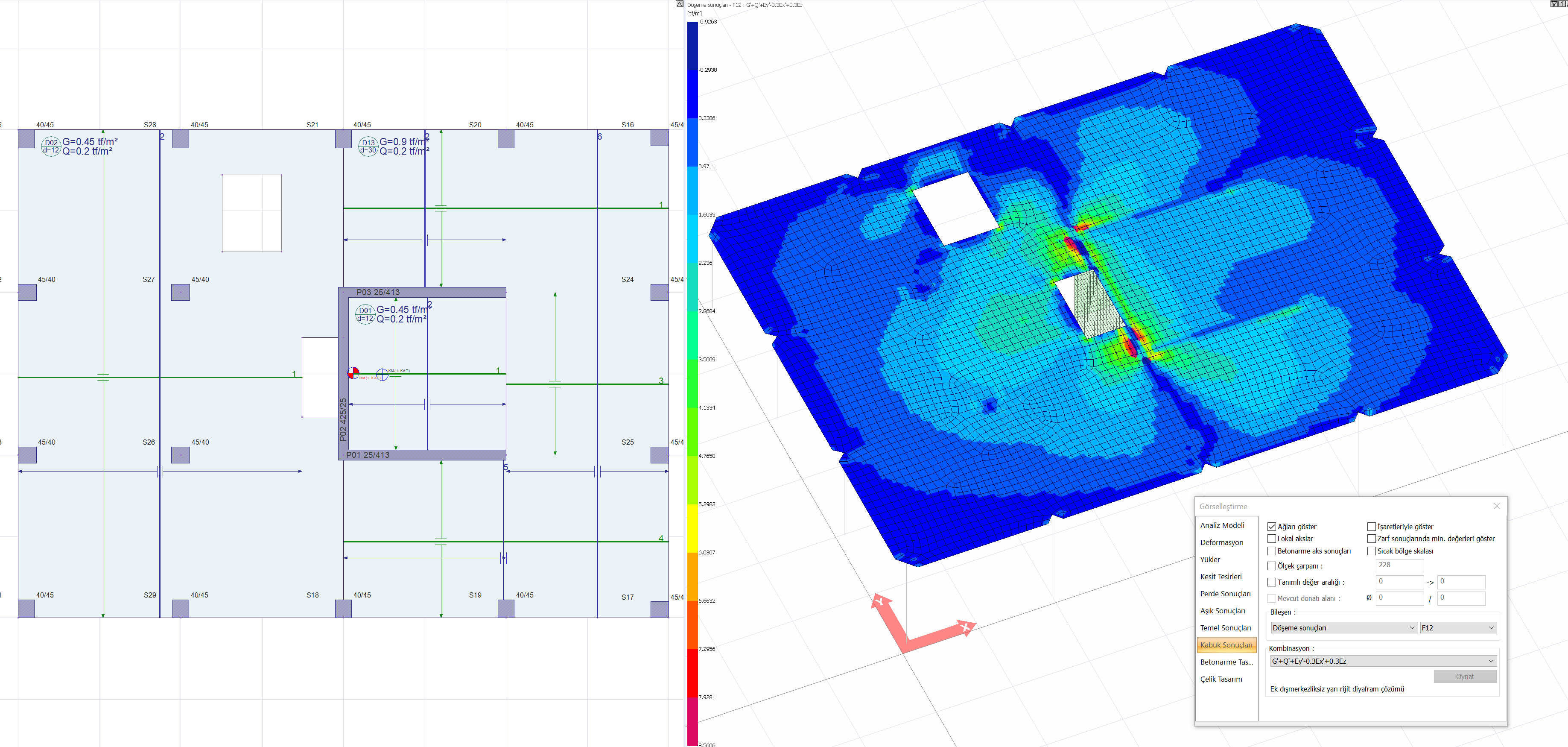
Floor spaces cause accumulation in floor stresses caused by vertical loads and earthquake loads. In the picture below , a floor plan is shown in which the case of "the presence of local floor gaps that make it difficult to transfer earthquake loads to vertical bearing system elements" in the definition of A2 type irregularity. Since there is a gap in the floor connected to the curtain, the in-plane shear stresses (F12) under the effect of an earthquake in the (Y) direction increase significantly at the gap edges as seen on the right side of the picture.
A2 type irregularity occurs due to floor gaps. For this reason, slab in-plane deformations were neglected. Rigid diaphragm solution is not applied in this type of irregularity. In buildings with A2 type irregularities, a semi-rigid diaphragm solution should be made in which the floors are modeled with shell finite elements .
According to Article 7.11.5 of TBDY , earthquake loads must be safely transferred from floors to vertical bearing elements. A floor plan in which A2 type irregularity definition consists of "the presence of local floor gaps that make it difficult to safely transfer earthquake loads to vertical bearing system elements" is shown in the above picture. The shear stresses accumulated in these spacesare also controlled by article 7.11.5 . When such gaps are opened in the critical areas of the vertical bearing elements, both 7.11.3 slab stress checks and 7.11.5 seismic loads are safely transferred from the floors to the vertical bearing elements.
Next Topic