
SYMBOLS
Pr: Required axial force resistance for YDKT or GKT load combinations
Pc: Strength of axial compressive force available according to Section 8
Mr: Required bending moment strength for YDKT or GKT load combinations
Mc: current bending moment strength according to Section 9
Design for Axial Force and Flexural Moment
-
The strength calculation is made by taking into account the combined stresses created in the members under a flexural moment and axial force.
-
The superposition of the stresses is only applicable to similar stresses.
-
The superposition rule does not apply to when stability losses occur.
Design with ÇYTHYE 2018
-
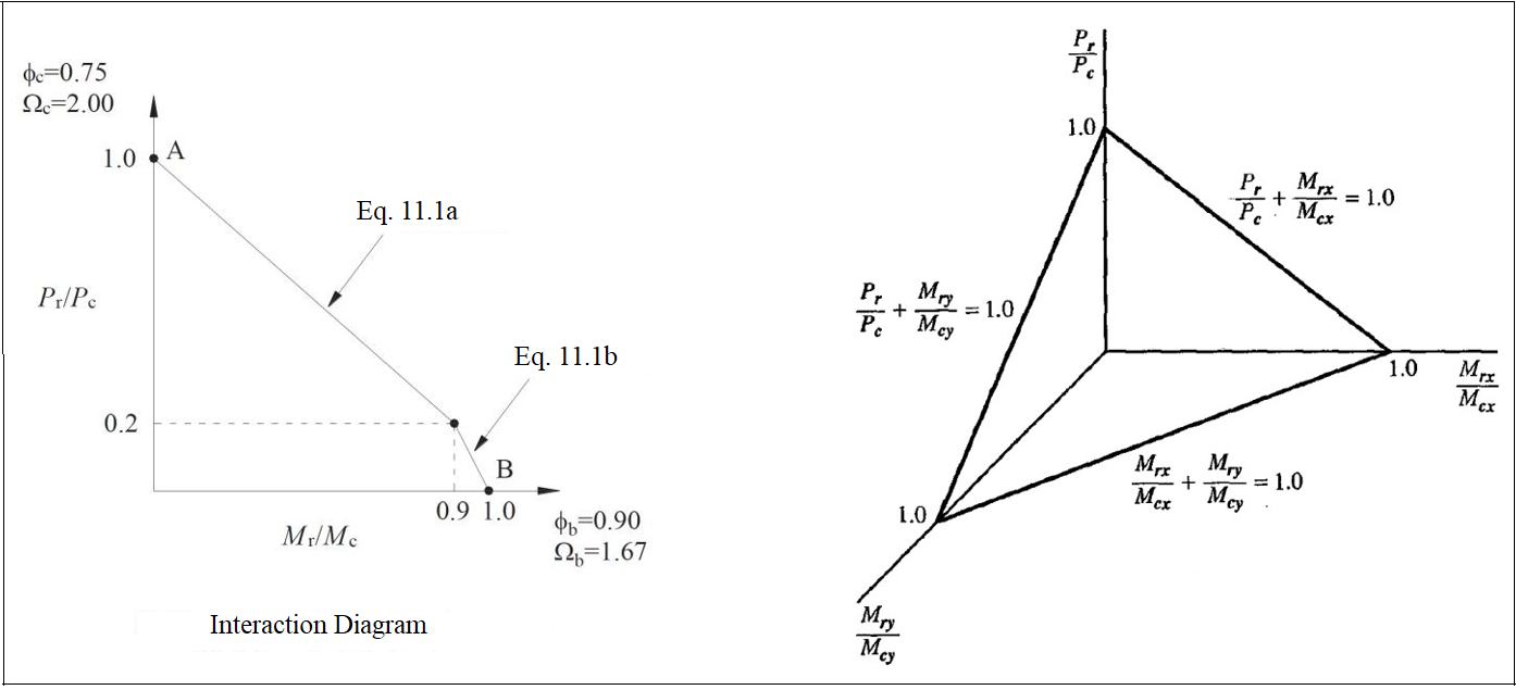
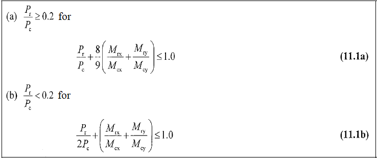
Equation 11.1 is used for double and single symmetrical members under the combined effect of compression and biaxial flexural moment.
Next Topic