
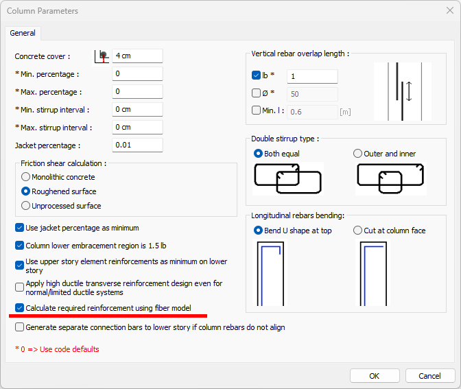
The required reinforcement area in the columns can be calculated using the Fiber model. When the Calculate Required Reinforcement Using Fiber Model option is activated in the Column Parameters dialog, the reinforcement area is calculated according to this calculation method.
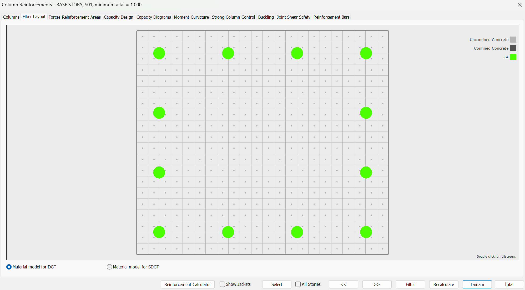
In the fiber model, the section is divided into concrete and reinforcement fibers as shown below.
Then, a more detailed section design calculation is made by using the Mander model, which is the material model defined in TBDY, and the conditions given in TS500.
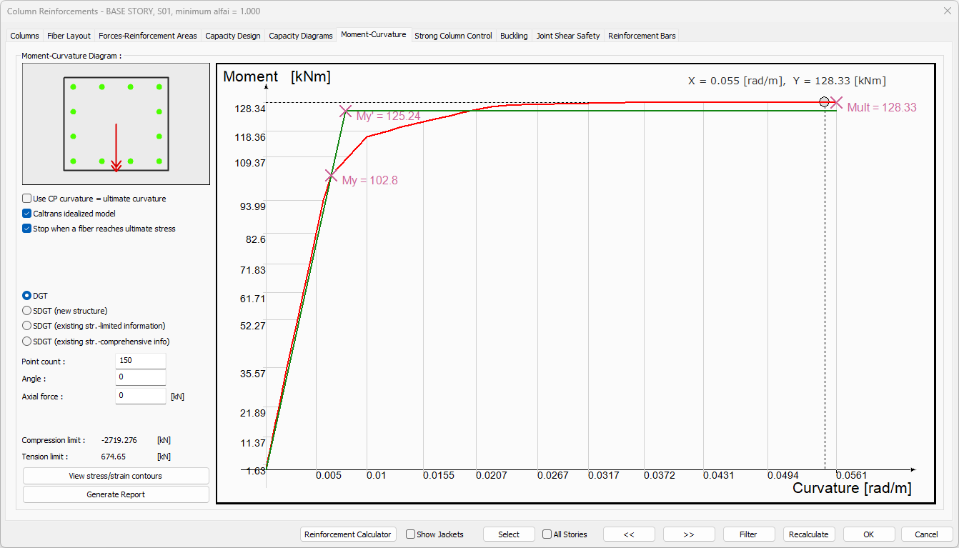
In the DGT approach, the design of the columns is made by calculating the moment strength calculated using the moment-curvature relation at each axial force level, according to the material conditions given in TS500 . The assumptions given in TS500 7.1 are as follows.
-
The tensile strength of concrete is neglected.
-
It is assumed that there is full adherence between the reinforcing bar and the surrounding concrete.
-
Plane sections remain plane after deformation.
-
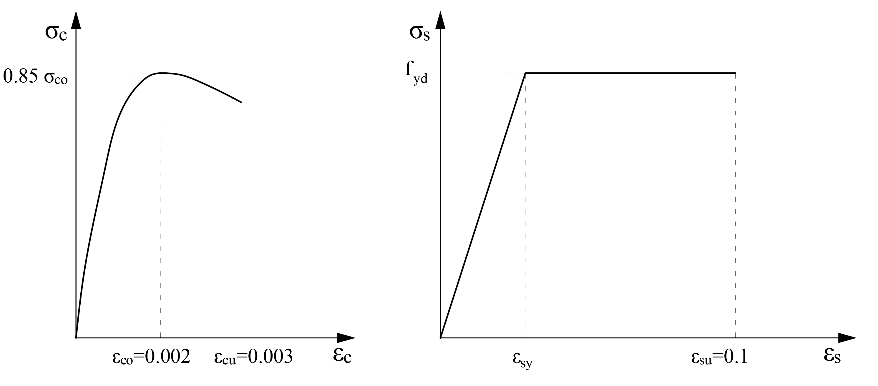
When the unit shortening in the concrete compressive fiber furthest from the neutral axis reaches εcu = 0.003 or the unit elongation at break of the reinforcement reaches εsu = 0.1, the element has reached its bearing capacity.
-
Reinforcing steel exhibits elastoplastic behavior.
-
σs ≤ fyd is σs = Es εs ≤ fyd
-
σs > fyd is σs = fyd
-
-
The modulus of elasticity of the reinforcement is Es = 200000 MPa.
-
The unconfined concrete model given in TBDY Annex 5A is used for the stress distribution in the concrete pressure region.
-
A concrete stress-strain graph is drawn so that the highest concrete compressive stress value is 0.85f cd .
Concrete and reinforcement material models are shown below.
With the material models given above, the moment-curvature analysis is performed using appropriate fibers and the bending moment strength of the section under the axial force and biaxial bending effect is found.
While the "Calculate the required reinforcement using the fiber model" option is not active, the concrete behavior is calculated as an equivalent rectangle in the method used, while a much more realistic concrete behavior model is used in the Fiber model.
The assumptions made in the calculation of the design forces under the effect of axial compression and biaxial bending calculated using the equivalent rectangle method are shown below. In the picture below, the calculation acceptance of a section under the influence of axial force and uniaxial bending is shown schematically. In ideCAD Structural, this calculation is made under the effect of axial force and biaxial bending.
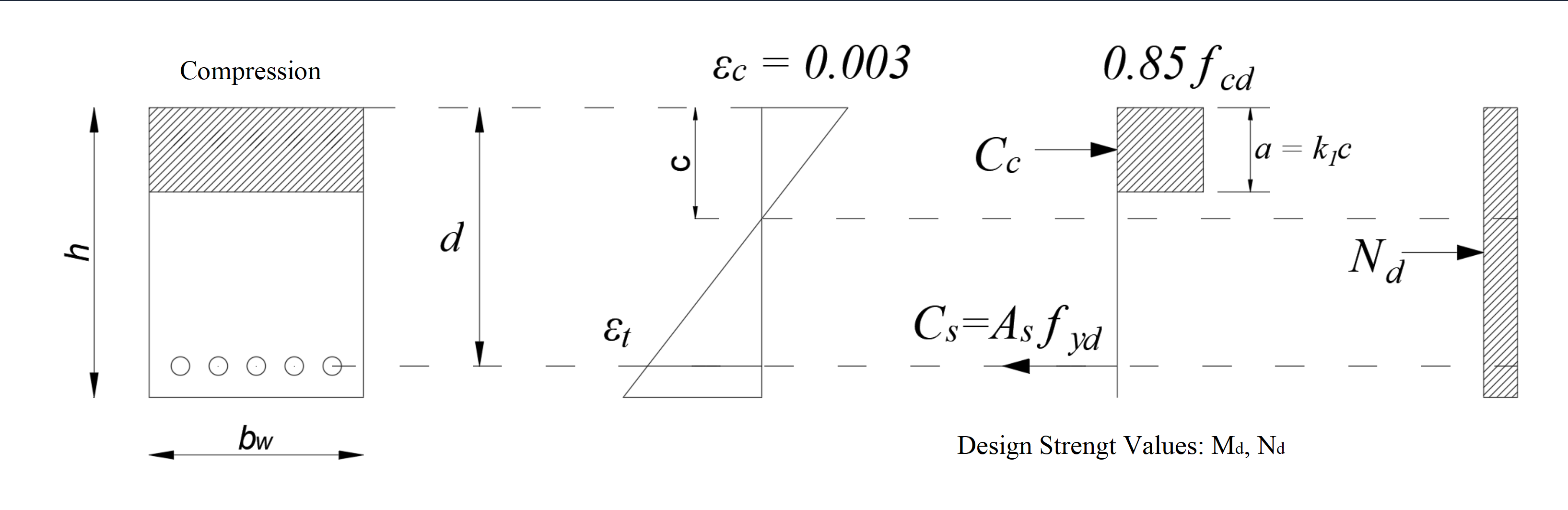
At the same time, capacity ratios can be calculated thanks to the interaction curve calculated by considering all combinations with the existing reinforcement placement of the element under the influence of axial force and biaxial bending. ideCAD Software takes this one step further and offers the opportunity to automatically select a reinforcement according to the interaction equation calculated with the fiber model.
Related Topics