-
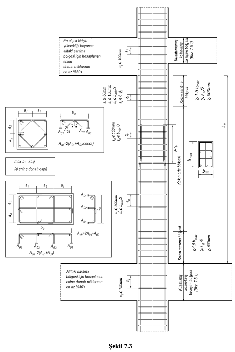
Conditions related to the minimum transverse reinforcement to be used in columns, column confinement regions are applied automatically as indicated in Figure 7.3 for column middle region .
-
Special earthquake hoops and special earthquake crossties defined along the entire column are used automatically.
-
Special confinement zones are automatically created at the lower and upper ends of each column in accordance with 7.3.4.1 .
-
The coiling area is automatically created at the lower end of the cantilever columns.
-
Conditions for the transverse reinforcement to be used in the confinement zones are applied automatically. These reinforcements are continued in the foundation along a height not less than the minimum size of the column.
-
Transverse reinforcement with a diameter smaller than ϕ8 is not used in confinement areas. In this region, the condition that the stirrups and crossties spacing in the longitudinal direction are not selected larger than 1/3 of the smallest section size, 150 mm, more than six times the longitudinal reinforcement diameter, and less than 50 mm are automatically applied.
-
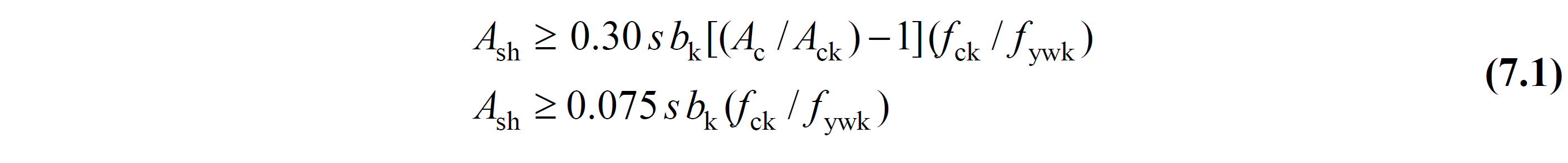
In case of N d > 0.20 A c f ck (pressure) in stirruped columns, the minimum total transverse reinforcement area in the confinement zones is automatically calculated in a way to provide the unfavorable conditions given in Equation (7.1) . In this calculation, the core size b k of the column is taken into account separately for both directions.
In case of N d > 0.20 A c f ck (pressure) in stirruped columns, the minimum total transverse reinforcement area in the confinement zones is automatically calculated in a way to provide the unfavorable conditions given in Equation (7.1) . In this calculation, the core size b k of the column is taken into account separately for both directions.
-
Not to use transverse reinforcement with a diameter smaller than ϕ8 in the middle of the column , The stirrup, crossover or spiral spacing along the column, taking the smallest cross-section size greater than half and 200 mm, and the horizontal distance between stirrup arms and / or crossties, a , stirrup diameter 25 The conditions are applied automatically.
Download ideCAD for ACI 318-19
ICONS
A c = Gross cross-section area of the column or wall end region
A ck = Core concrete area within the measure taken outside the outer of the confinement reinforcement
A sh = s along the height corresponding to the transverse reinforcement range, taking into account the cross-sectional area values of all hoops and crossties in the column or the sum of the projections in the perpendicular direction
b k = Cross-section dimension of the column or wall end zone core (distance between the outermost transverse reinforcement axes) for each of the perpendicular horizontal directions
b w =Width of the column in the direction of transverse reinforcement calculation
f ck = Characteristic cylinder compressive strength of concrete
f ctd = Design tensile strength of concrete
f ywk = Characteristic yield strength of transverse reinforcement
N d = Axial force calculated under the combined effect of vertical loads and earthquake loads multiplied by load coefficients
s = Transverse reinforcement spacing, spiral / wrapping reinforcement pitch
ρ = reinforcement ratio
ρ s = volumetric ratio of spiral reinforcement in the column
ϕ = Diameter of reinforcement
Transverse Reinforcement Conditions
Colon coiling zone
Coiling zones are formed at the lower and upper ends of each column . The length of each of the confinement zones is arranged such that the length is not less than 1/6 of the column free height, 1.5 times the largest section size of the column, and 500 mm. In cantilever columns, the confinement zone is formed at the lower end of the column, and the confinement zone is arranged so that its length is at least twice the size of the column.
Transverse reinforcement with a diameter smaller than ϕ8 is not used in confinement areas. In this region, the stirrups and crossties spacing in the longitudinal direction are not selected as 1/3 of the smallest section size, greater than 150 mm, greater than six times the longitudinal reinforcement diameter, and less than 50 mm. The horizontal distance between the stirrup arms and / or crossties, a, is not taken larger than 25 times the stirrup diameter.
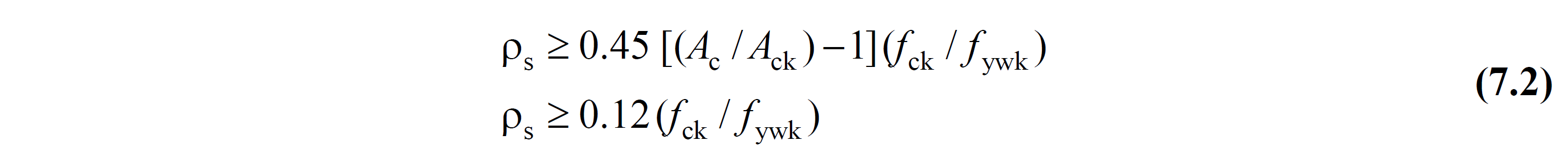
The minimum volumetric ratio A sh calculation changes depending on whether the condition N d > 0.20 A c f ck is met in both directions of the column . In each of the major and minor axes of the column:
N d > 0.20 A c f ck ise :
For columns with rectangular reinforcement:
In circular reinforced columns:
If N d ≤ 0.20 A c f ck ;
In case of N d ≤ 0.20 A c f ck , at least 2/3 of the transverse reinforcement calculated with Equation (7.1) and Equation (7.2) will be used as minimum transverse reinforcement in the column confinement regions .
A sh = 2/3 A sh or ρ ≥ 2 / 3ρ.
Reinforcement spacing is determined according to the transverse reinforcement diameter selected for confinement zones using A sh .
s = Number of Transverse Reinforcement * Transverse Reinforcement Area / A sh
Middle column
The middle region of the column is the region between the confinement regions defined at the lower and upper ends of the column. The central column transverse reinforcement conditions are determined according to 7.3.4.2 .
Transverse reinforcement with a diameter smaller than ϕ8 is not used in the middle of the column. The stirrup, crossover or spiral spacing along the column is not taken larger than half of the smallest cross-section size and 200 mm, and the horizontal distance between the stirrup arms and / or crossties, a , is not made more than 25 times the stirrup diameter.
The column is also checked for the minimum condition given in the TS500.
Asw/s > 0.3 bw * fctd / fywk
Special earthquake hoops and crossties
Special seismic hoops and crossties defined in 7.2.8 are used along the entire column .
The conditions required to be met by special earthquake hoops and crossties are given in Figure 7.1 .
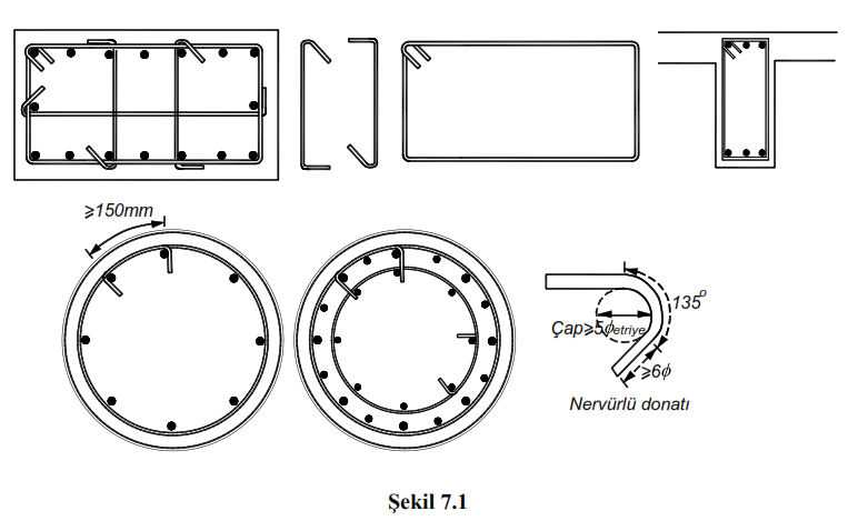
135 degree curved hooks are made at both ends of special earthquake hoops . The internal bend diameter of 135 degree bent hooks, φ to indicate the diameter of the transverse reinforcement, is taken at least 5ϕ. The end straight length of the hooks is not taken less than 6ϕ and 80 mm in ribbed bars, starting from the final tangent point in the fold ( Figure 7.1 ).
Special seismic hoops will grasp the longitudinal reinforcement from the outside and the hooks are closed around the same longitudinal reinforcement. The diameter and spacing of special earthquake crossties are taken the same as the diameter and spacing of stirrups. The crossties are prepared at both ends in an order that will necessarily surround the longitudinal reinforcements and the outer stirrup.
Transverse reinforcement intervals in the column cannot exceed the following conditions. ( Figure 7.3 ).