
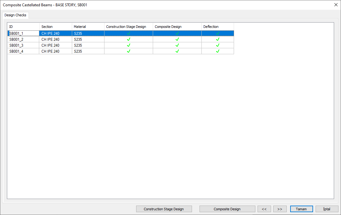
Composite castellated beam design results and inadequacies of composite castellated beams are displayed in the Composite Castellated Beams dialog. If the sections of the secondary beams are selected as castellated beams and composite slab is defined on these secondary beams, the composite castellated beam design is used. In the Composite Castellated Beams dialog, shearing in the gross and net area, body buckling, vierendeel controls, internal force results and net moment of inertia calculation are also given.
Location of Composite Castellated Beam Dialogue
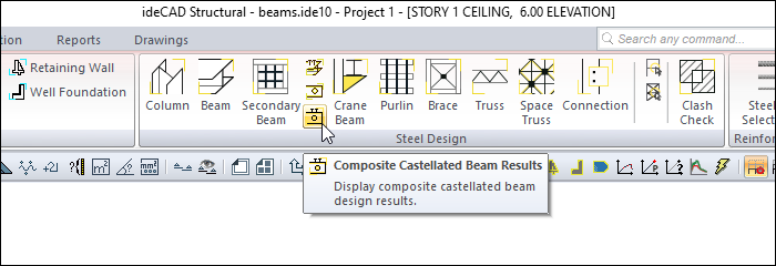
After the analysis is done, you can access it by clicking the Composite Castellated Beam Results command under the Steel Design heading in the ribbon menu Analysis and Design tab .
Composite Castellated Beams
|
Specifications |
|---|
|
ID 
Castellated beam is the name of the beam in the plan. |
|
Section 
It is the section used in castellated beam. |
|
Material 
Castellated beam is the material class of the beam. |
|
Construction stage design 
The construction stage shows the design control. |
|
Composite design 
Demonstrates composite design control. |
|
Deflection 
Shows castellated control. |
|
Construction stage design The construction phase opens the design details window. |
|
Composite design Opens the composite design details window. |
|
Previous The cursor moves to the previous line. |
|
Next The cursor goes to the next line. |
|
OK It saves the changes made and closes the dialog. |
|
Cancel Closes the dialog without saving the changes made. |
|
Summary Information The summary information about the line where the cursor is located is given in the name of the dialog in story, pose format. 
For example, BASE STORY, SB001 |
|
Using the Shift key In this tab, you can select more than one row with the Shift key, enter a value by double-clicking any cell whose value is open to change, and make that value apply to all selected rows. |
|
Using the Ctrl key Ctrl key selects the lines in between one by one. |
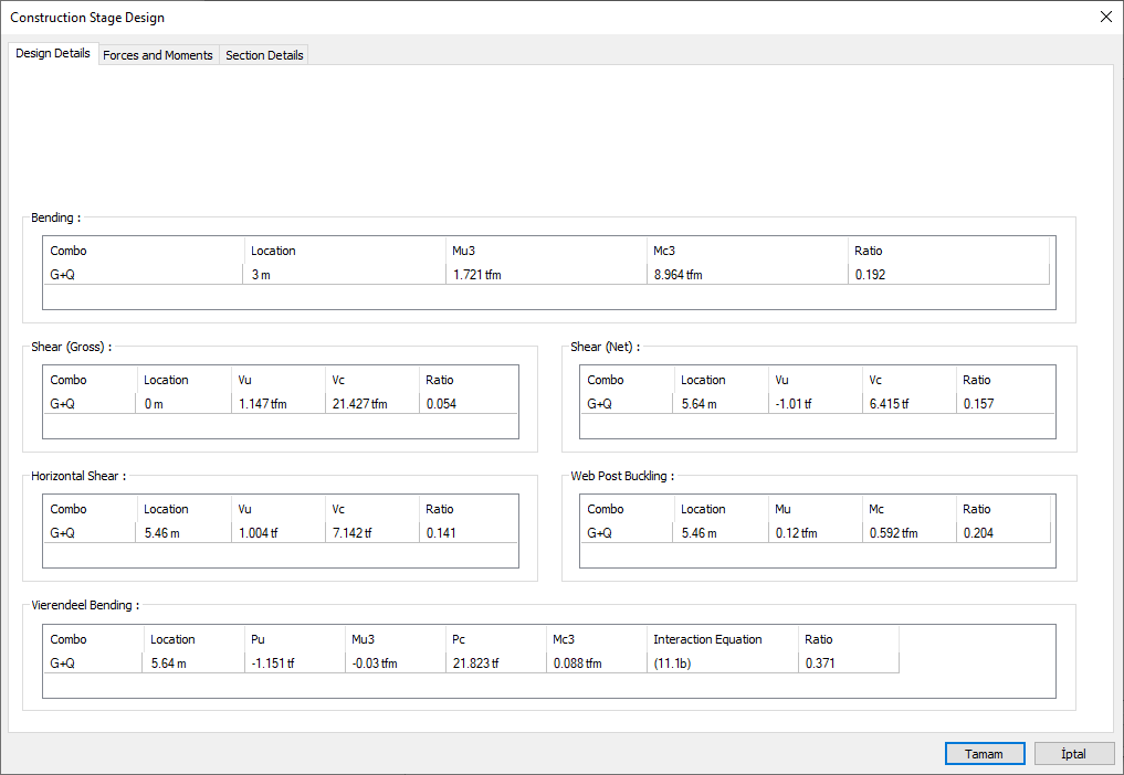
Construction Stage Design
Design Details Tab
|
Specifications |
|---|
|
Bending 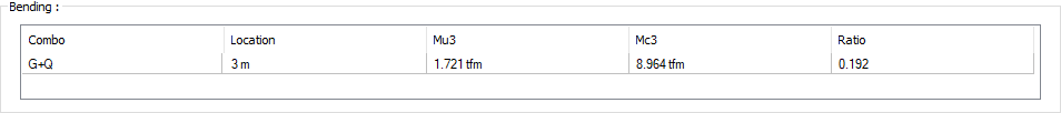
Combo: It is the combination that creates the most unfavorable section forces.
|
|
Shear (Gross) 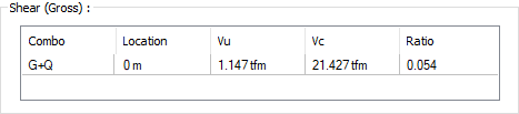
Combo: It is the combination that creates the most unfavorable section forces.
|
|
Shear (Net) 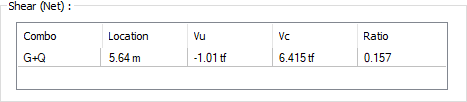
Combo: It is the combination that creates the most unfavorable section forces.
|
|
Horizontal shear 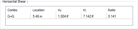
Combo: It is the combination that creates the most unfavorable section forces.
|
|
Web post buckling 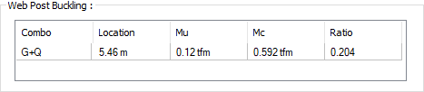
Combo: It is the combination that creates the most unfavorable section forces.
|
|
Vierendeel bending 
Combo: It is the combination that creates the most unfavorable section forces.
|
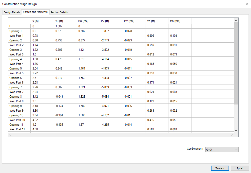
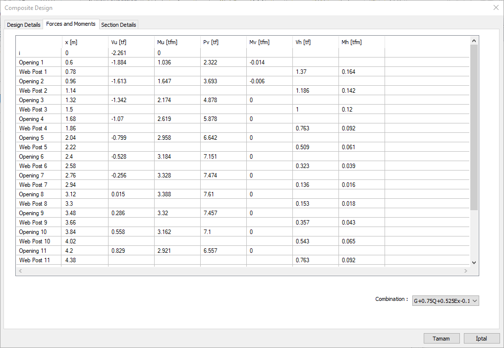
Forces and Moments Tab
|
Specifications |
|---|
|
i 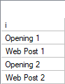
The web post and opening in the castellated beams are listed. |
|
x 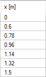
It shows the location where the relevant forces and moments are located. |
|
Vu 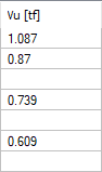
It is the shear force acting on the element. |
|
Mu 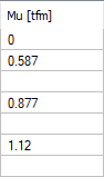
It is the moment value acting on the element. |
|
Pv 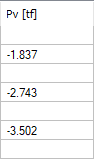
It is the axial force value. |
|
Mv 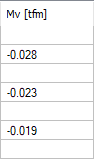
It is the moment value acting on the element. |
|
Vh 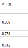
Shear force acting on the element. |
|
Mh 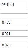
It is the moment value acting on the element. |
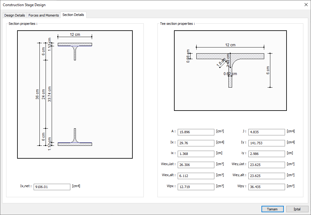
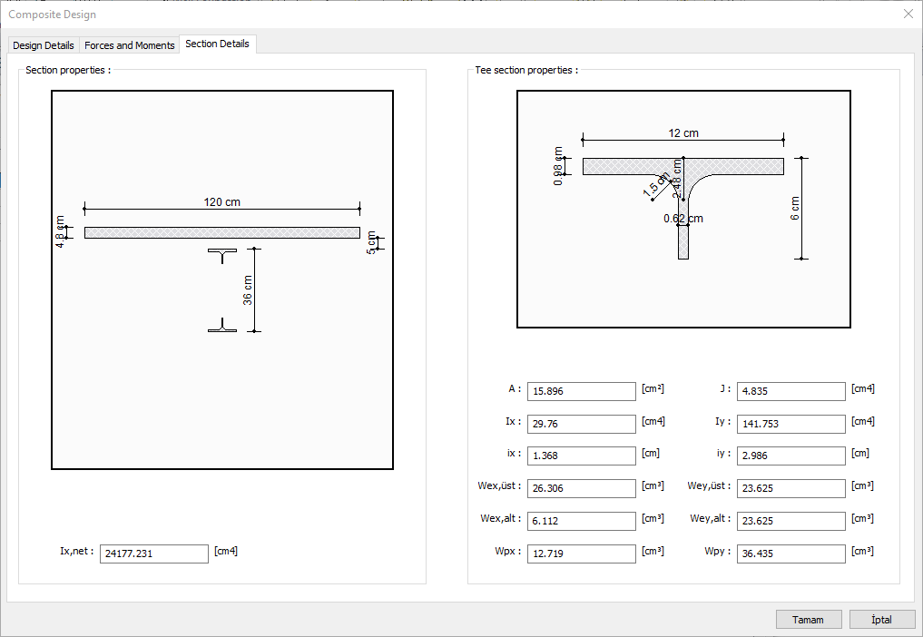
Section Details Tab
|
Specifications |
|---|
|
Section properties 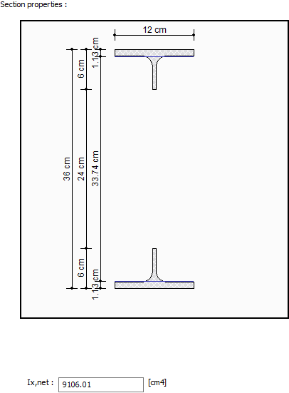
Ix, net: shows the net moment of inertia in the x direction. |
|
T section properties 
A: Shows the cross section area.
|
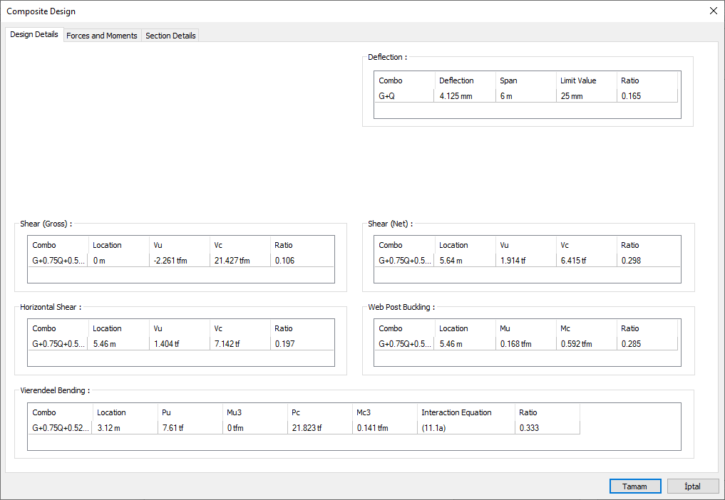
Composite Design
Design Details Tab
|
Specifications |
|---|
|
Deflection 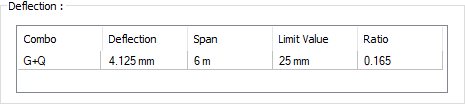
Combo: It is the combination that creates the most unfavorable section forces.
|
|
Shear (Gross) 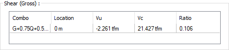
Combo: It is the combination that creates the most unfavorable section forces.
|
|
Shear (Net) 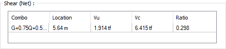
Combo: It is the combination that creates the most unfavorable section forces.
|
|
Horizontal shear 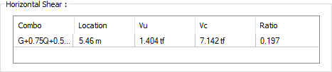
Combo: It is the combination that creates the most unfavorable section forces.
|
|
Web post buckling 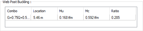
Combo: It is the combination that creates the most unfavorable section forces.
|
|
Vierendeel bending 
Combo: It is the combination that creates the most unfavorable section forces.
|
Forces and Moments Tab
|
Specifications |
|---|
|
i 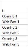
The web post and openning in the castellated beam are listed. |
|
x
It shows the location where the relevant forces and moments are located. |
|
Seen 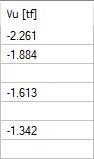
It is the shear force acting on the element. |
|
Mu 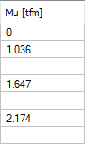
It is the moment value acting on the element. |
|
Pv 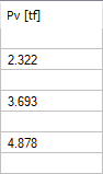
It is the axial force value. |
|
Mv 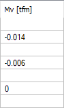
It is the moment value acting on the element. |
|
Vh 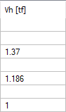
Shear force acting on the element. |
|
Mh 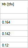
It is the moment value acting on the element. |
Section Details Tab
|
Specifications |
|---|
|
Section properties 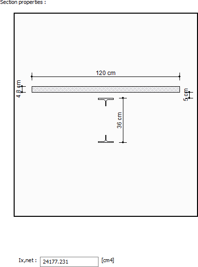
Ix, net: shows the net moment of inertia in the x direction. |
|
T section properties 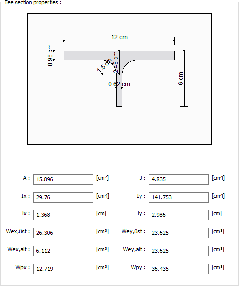
A: Shows the cross section area.
|
Next Topic
Related Topics